Vr Mapping |
ON-LINE REFERENCE DOCUMENTATION CARDINAL SYSTEMS, LLC |
Batch Attach (BatAtt)
Type: Batch Application
Attaches source line end segments to target lines.
Detailed Description
Batch Attach is useful for attaching certain types of map features such as building decks and pads to buildings. Options include the ability to copy common points from the target lines (buildings) to the source lines (decks). Noding and Z-Rules are supported.
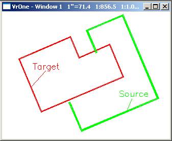

In the above example the red line is the target line and the green line is the source line. The source line under-shoots the target line at the lower node and over-shoots the target line on the upper node. The resulting attach in the second windows shows the attachment of the source line to the target line and the optional “Copy common line segments” and “Node target lines”.
Available Key-ins
Key-in |
Description |
Range |
PARFIL= |
Load parameter file |
Batch Attach parameter file name (.btt) |
RUN |
Run Batch Node |
|
Parameters for Batch Attach
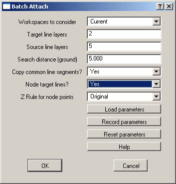
Workspaces to consider
Defines the workspaces to consider when running batch node.
Target Layers
Layers containing lines that will be attached to. These lines are considered line 1 for the Z rule. A number line may be used to define the layers.
Source Layers
Defines the layers containing lines to attach to target lines. These lines are considered line 2 for the Z rule. A number line may be used to define the layers.
Search Distance
Defines the distance to search from the target lines for source lines.
This parameter is used to find undershoots and is set in ground units.
NOTE: The Search Distance should be kept as small as possible. Unexpected results may occur if this parameter is unreasonable.
Copy Common Line Segments
If this parameter is set to “Yes” then common line segments from the target line will be copied to the source line. This will make the source line a closed polygon.
Node Target Lines
If this parameter is set to “Yes” then a common point will be placed on the target line. This common point will be the end points of the source line.
Z Rule
This rule is used for computing the elevation at the intersection of the two lines. During attach, an elevation for each line is computed at the intersection point. These elevations are based on the slope of the line segment as determined by the point before and after the break point. The Z Rule determines the action to be taken on these two elevations as follows:
| • | Original elevations – The elevations of the break points are not modified. |
| • | Mean node elevations – The elevations are averaged and stored for both node points. |
| • | Elevation from line 1 – The elevation from the node point on line 1 is used on both lines. |
| • | Elevation from line 2 – The elevation from the node point on line 2 is used on both lines. |