Vr Mapping |
ON-LINE REFERENCE DOCUMENTATION CARDINAL SYSTEMS, LLC |
Batch Common (BatCom)
Type: Batch Application
Processes common and orphaned node points between lines.
Detailed Description
Batch Common finds and corrects mismatched node points and finds and corrects orphan node points between lines. The application automatically searches for both common and orphan points from both the source lines to the target lines and from the target lines to the source lines. Options include the ability to specify source and target layers, a minimum distance in which points are considered common, Xy and Z search distances, Xy and Z rules.
Corrective actions include the ability to mean common points, move source points to target points or move target points to source points. These actions may be taken in both the Xy and Z axis. A drive file will be created when running Batch Common so the mismatched points many be viewed.
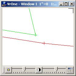
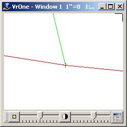
Common Points
The following is an example of a common point mismatch. In this case the node points exist but are not matched. The example on the left shows the mismatched points and the example on the right shows the corrective action using the mean option.
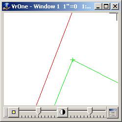
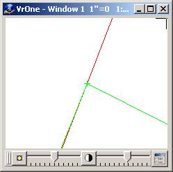
Orphan Points
The following is an example of an orphan point. In this case the node point exists on only one line. The example on the left shows a node point on the green line and the absence of a corresponding node point on the red line. The example on the right shows the corrective action of placing a node point on the red line and then using the mean option to match the two points.
Available Key-ins
Key-in |
Description |
Range |
PARFIL= |
Load parameter file |
Batch Common parameter file name (.btc) |
RUN |
Run Batch Node |
|
Parameters for Batch Common
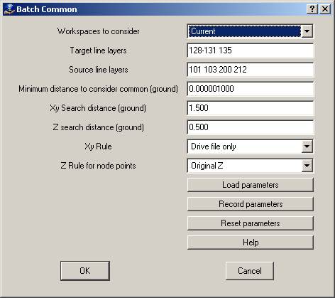
Workspaces to consider
Defines the workspaces to consider when running batch node.
Target Layers
Defines the layers containing the target lines, which will be checked against source lines. A number line may be used to define the layers. When running Batch Common, points on the source lines are compared to the points on the target line then points on the target lines are compared to the points on the source lines.
Defines the layers containing lines to attach to target lines. A number line may be used to define the layers. When running Batch Common, points on the source lines are compared to the points on the target line then points on the target lines are compared to the points on the source lines.
Minimum Distance To Consider Common
When testing points for commonality this distance is used to determine if two points are common. If the computed distance between two points is less than this value then the points will be considered common. This value should be very small and is expressed in ground units.
Xy Search Distance
If the computed Xy distance between two points is greater than the Minimum Distance and less than the Xy Search Distance then the points will be considered mismatched in the Xy direction. If the points are also mismatched in the Z direction then the Xy and Z Rules will be applied to the two points. This value is expressed in ground units.
If the computed Z distance between two points is greater than the Minimum Distance and less than the Z Search Distance then the points will be considered mismatched and the Z direction. If the points are also mismatched in the Xy direction then the Xy and Z Rules will be applied to the two points. This value is expressed in ground units.
Xy Rule
This rule is used for computing the position of the node points in the Xy direction.
| • | Drive file only – The node points are not changed in either the Xy or Z directions and only a drive file is created. |
| • | Original Z – The elevations of the common points are not modified. |
| • | Mean points – The points are placed at the mean Xy location between the two points. |
| • | Move source point to target point – The Xy position from the source line will be used for both points. |
| • | Move target point to source point – The Xy position from the target line will be used for both points. |
This rule is used for computing the elevation of two node points.
| • | Original Z – The elevations of the common points are not modified. |
| • | Mean Z – The elevations are averaged and stored for both node points. |
| • | Move source Z to target Z – The elevation from the source line will be used for both points. |
| • | Move target Z to source Z – The elevation from the target line will be used for both points. |