Vr Mapping |
ON-LINE REFERENCE DOCUMENTATION CARDINAL SYSTEMS, LLC |
Getting Started With ADS40
This document explains the process for using ADS40 stereo images with VrTwo. This document will walk through the steps required to load in ADS40 images and support files to allow collection of mapping features in VrTwo. Before beginning this tutorial, please review the main Getting Starting Tutorial for background information regarding Vr Mapping software. This document will provide the required information to create VrTwo ADS40 model files from ADS40 Level One images and support files, and collect vector data with VrTwo using the ADS40 stereo model.
Mapping Work Flows
There are several work flow paths that can be taken to start with a stereo pair images to finished mapping product. The work flows depend on the type of starting images and the way they will be oriented to the project coordinate system. Several other work flows are discussed in the main Getting Starting Tutorial. This tutorial will cover the ADS40 work flow only.
ADS40 Work flow
When starting an ADS40 based project, images and support files produced by third party ADS40 processing software should already be on hand. Normally, this software would be either GPro or XPro from Leica Geosystems.
| 1. | ADS40 Model Setup - The model setup is performed inside VrTwo using the Open ADS Model (OpeAds) command. An ADS model file is required for each ADS40 stereo image pair. |
| 2. | Collect mapping data in VrTwo - VrTwo is used to open the model files and place mapping features from the stereoscopic 3D view. |
| 3. | Clean mapping data and prepare for delivery - VrOne is used to perform batch clean up operations, generate contours if required, and assemble together final map sheets. |
Tutorial Overview
The tutorial will provide information on the steps of creating a new VrTwo ADS model from standard ADS support files. In the production ADS40 work flow, GPro or XPro will generate support files and images required by VrTwo. This tutorial provides the support files and images that were generated from GPro. On a production job, there are normally multiple image pairs and support files for each flight line. A VrTwo ADS model is required for each stereo image pair. The tutorial only walks through the process of setting up one model.
| • | Level One stereo viewable TIFF images. These are normally panchromatic images and come in backward and forward pairs. The backward looking image will usually have PANB in the filename. The forward looking image will normally have PANF in the filename. Each filename will normally have the flight line number and model number embedded in the name. For example, the left and right image filenames for model one in flight line one may end with "_1_1". |
| • | Support (.sup) files. One for the each image. The filenames usually match or be similar to the left and right image names. |
| • | ADS40 orientation data files (.odf). One for each image, and the filenames should be similar to the image filenames. |
| • | ADS40 image definition files (.ads). One one for each image, and the filenames should be similar to the image filenames. |
| • | Optional ADS40 adjusted orientation data files (.odf.adj). If these are present there will be one for each image, and the filenames should be similar to the image filenames. |
| • | Two Camera calibration files (.cam). These files are usually named PANB14A and PANF28A. |
| • | Control file. This is a standard VrTwo control file (.vr) containing known control points in the project. |
The support files are the primary files used by VrTwo. They define the locations of the other required files. Although the support files will already contain links to the other required files, they may not be on the same location on your computer as they are defined in the support file. When adding support files to a new ADS model definition, VrTwo tries to locate the files in the folders located at or below the ADS model file location. If VrTwo cannot find the files required by the Left and Right support files, the file locations will need to be set up manually. This is explained in the tutorial walk through.
Tutorial Walk Through
Download the sample Data
To get started, download the sample data and install it to your local computer. The sample data for this project can be download at the following address.
http://vrdownload.cardinalsystems.net/downloads/sample-data/gettingstartedads40model.exe
Please contact Cardinal Systems for the username and password for this download.
Install the Sample Data
| 1. | Run the gettingstartedads40model.exe file. This will install the sample data into c:/jobs/sampleads40model. |
The sample data consist of the following files.
| • | Two ADS40 level one images (.tif) |
| • | Two ADS40 support files (.sup) |
| • | Two ADS40 camera calibration files (.cam) |
| • | Two ADS40 orientation data files (.odf) |
| • | Two ADS40 adjusted orientation data files (.odf.adj) |
| • | Two ADS40 image definition files (.ads) |
| • | Control file |
ADS40 requires Geoid files to be installed. If you have not installed the Vr Mapping Geoid files, follow these steps:
| 1. | Go to the www.cardinalsystems.net website. |
| 2. | Select Support->Download Vr Mapping Software |
| 3. | Accept the Cardinal Systems Software License and Software Support Agreement. |
| 4. | Enter user name and password for downloading Vr Mapping software. |
| 5. | Navigate to vrsoftware/data and select the geoid-1.0.exe file. |
| 6. | Download geoid-1.0 into a temporary folder on your computer (normally the downloads folder on Windows 7) |
| 7. | Run geoid-1.0.exe and install to the default location. The password is the same as the Vr Mapping install software. |
Now that the sample data has been installed, VrTwo will be used to create an ADS model file and then display the ADS40 stereo images.
Start VrTwo
| 1. | Double click on the Vr Mapping folder on your desktop. |
| 2. | Double click on the VrTwo Icon in the opened Vr Mapping folder. |
The VrTwo Main Window will now be displayed along with one or more graphics windows as shown below.
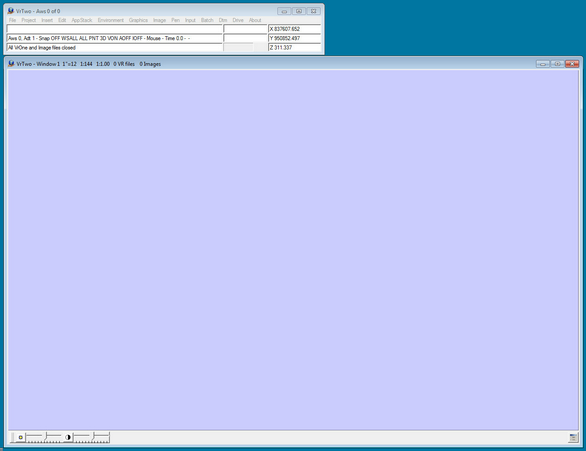
VrTwo Main Window and Graphics Window with no model or VrOne vector file open.
Create ADS40 model file
In order to view the ADS stereo images, a model file must be created in VrTwo. This model file defines the two support files and two images that make up a single ADS stereo model along with the project datum.
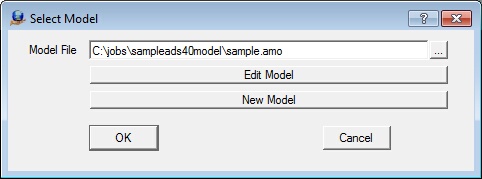
| 1. | Click on File then Open the ADS model. This can also be done with the Open ADS (OpeAds) command. |
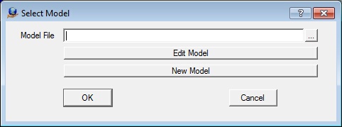
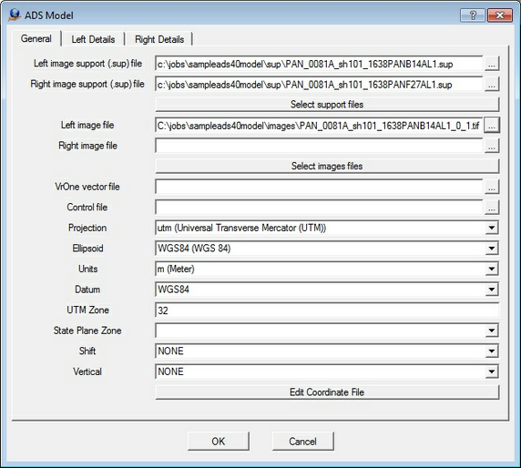
| 2. | Select the "New Model" button which will display the ADS model definition dialog box. |
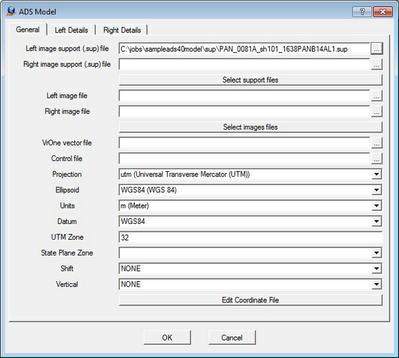
This dialog box contains three tabs. The General tab defines the model itself and the Left and Right Details tabs allow the editing of the details of the left and right support (.sup) files.

| 3. | Press the "..." button next to Left image support (.sup) file field to display the file selection dialog box. |
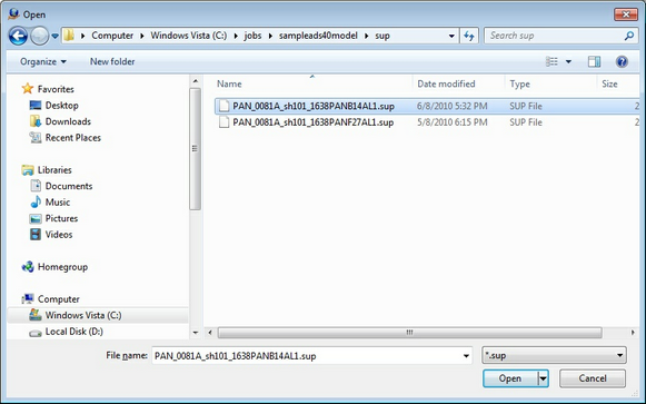
| 4. | Navigate to the c:/jobs/sampleads40model/sup folder and open the PAN_0081A_sh101_1638PANB14AL1.sup file. |
| 5. | Press the "..." button next to Right image support (.sup) file field to display the file selection dialog box. |
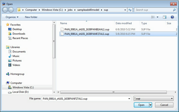
| 6. | Navigate to the c:/jobs/sampleads40model/sup folder and open the PAN_0081A_sh101_1638PANF27AL1.sup file. |
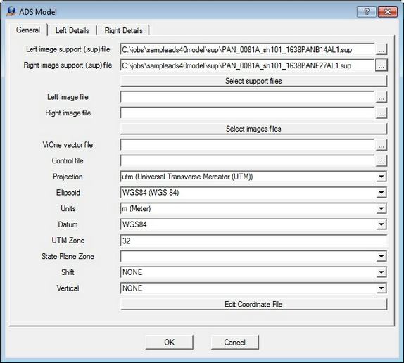
NOTE: The "Select support files" button may be used to select the left and right support files in one step.
| 7. | Press the "..." button next to Left image file field to display the file selection dialog box. |
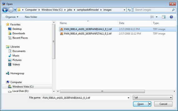
| 8. | Navigate to the c:/jobs/sampleads40model/sup folder and open the PAN_0081A_sh101_1638PANB14AL1_0_1.tif file. |
| 9. | Press the "..." button next to Right image file field to display the file selection dialog box. |
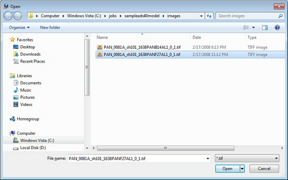
| 11. | Navigate to the c:/jobs/sampleads40model/sup folder and open the PAN_0081A_sh101_1638PANF27AL1_0_1.sup file. |
| 12. | Navigate to the c:/jobs/sampleads40model/images folder and open PAN_0081A_sh101_1638PANB14AL1_0_1.tif and PAN_0081A_sh101_1638PANF27AL1_0_1.tif. |
Make sure the PAN_0081A_sh101_1638PANB14AL1_0_1.tif file is selected first.
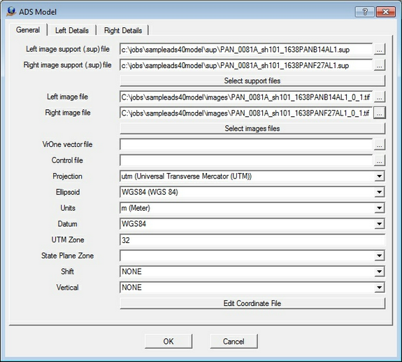
| 13. | Type in "c:\jobs\sampleads40model\model1.vr" in the "VrOne vector file" field. A VrOne vector (.vr) file has not been created yet, so the name used |
in the "VrOne vector file" field will be used to create a new VrOne vector file when the model is first opened.
| 14. | Press the "..." button next to the "Control file" field to display the file selection dialog box. |
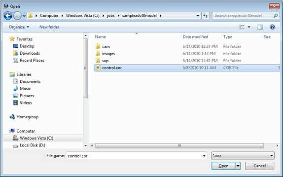
| 15. | Navigate to the c:/jobs/sampleads40model/ folder and open the control.cor ground control file. |
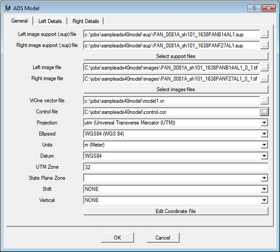
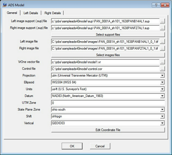
| 16. | Normally, at this stage, the datum for your project coordinate system would be input. For this sample project, the following datum is used: |
Projection: UTM
Ellipsoid: WGS84
Units: US Surveyor's Foot
UTM Zone: 0
State Plane Zone: 3402
Shift: Ohio south
Vertical: GEOID03
Fill in the dialog to match the values above.
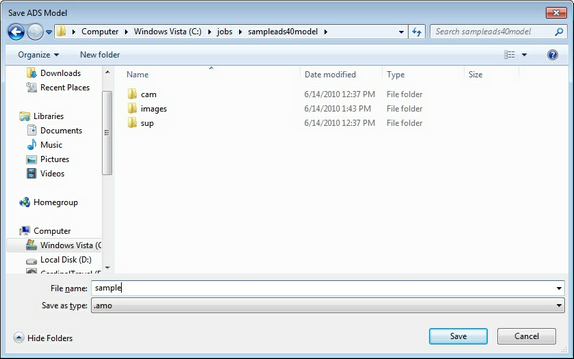
| 17. | Press the OK button which will display a dialog box to confirm the saving of the parameters. |
| 18. | Navigate to the c:\jobs\sampleads40model\ folder and type in "sample" for the file name. |
| 19. | Select Edit Model to view the model settings dialog again. |
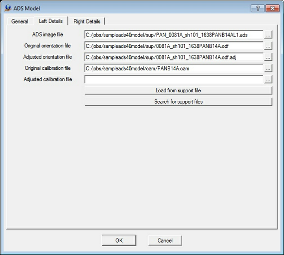
| 20. | Select the "Left Details" tab to view the settings in the left support file. On a normal project, it may be required to modify these settings to match the actual location of your ADS files. If needed, use the "Search" button to fix the path if the project has been moved from another location. This will search for the file names listed and apply the correct path to them. |
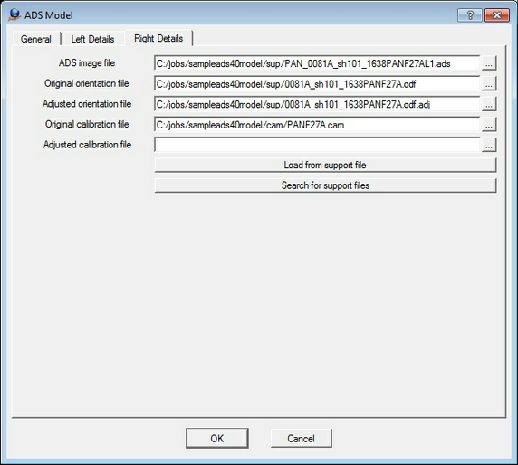
| 21. | Select the "Right Details" tab to view the settings in the right support file. |
| 22. | Press OK to close the model dialog. |
| 23. | Press OK open the sample model file. It may take a minute to build image pyramids if needed. |
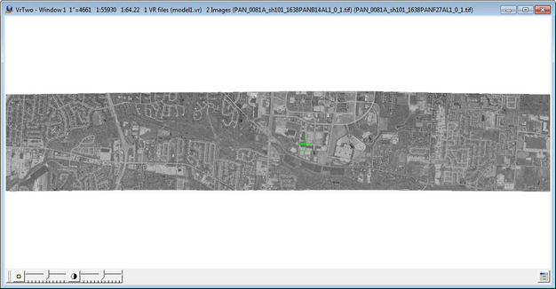
| 24. | Use the Zoom All command (ZooA) to zoom to the extents of the model. The graphics display should look like the following screen shot. |
If using stereo shutter glasses with an emitter, the emitter light will turn on, and the content should be viewable in 3D using the shutter glasses.
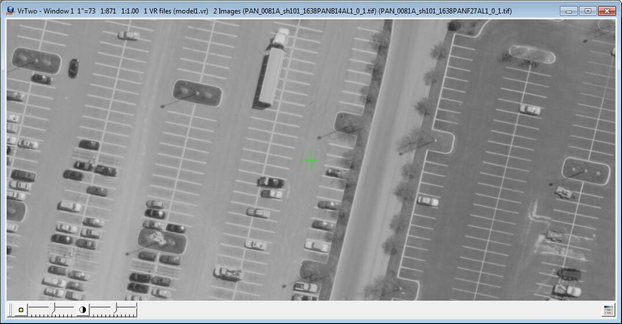
| 25. | Use the Display Image (DisIma 1) command to display the images at 1:1. |
| 26. | The Control Drive (Cd 1) command can be used to drive to the first control point. The display should look similar to this, with the cursor positioned as shown. In a normal project, the Control Drive (Cd 1) command would drive to an actual control point. For this tutorial, the control point location is just a random location selected for the purpose of this demonstration. |
| 27. | The VrOne/VrTwo standard collection tools along with Function Keys may now be used to start placing map features. |