Vr Mapping |
ON-LINE REFERENCE DOCUMENTATION CARDINAL SYSTEMS, LLC |
Insert Edge (InsEdg)
Type: Semi-automatic interactive application
Detailed Description
Semi-automatic tracing of lines along edges in LiDAR data. The user roughly identifies two points along the edge and the algorithm traces it in both directions until termination/failure. The result can be interactively navigated for quality control and possible editing.
Insert Edge is designed to work with LiDAR and point cloud data. This application may be started from a Function Key.
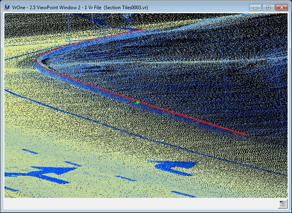
Top of curb edge
Button Assignments
Insert Edge – Main
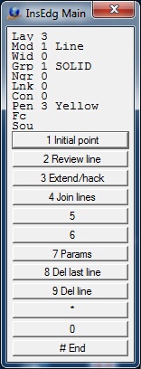
Main Menu
When Insert Edge starts, initial points along the edge line need to be digitized. This initial data provides seed information so the application can follow the edge and place a 3D line.
|
Button |
Description |
1 |
Initial point |
Identifies two points along the edge to provide initial data to start the edge line insertion. |
2 |
||
3 |
Review line |
Review an existing line |
4 |
Extend/hack |
Extend or hack an existing line |
5 |
Join lines |
Joins two existing lines using a user defined join point |
6 |
|
|
7 |
Enter params |
Enter/edit Insert Edge parameters (see Insert Edge Parameters) |
8 |
Del last line |
Deletes the last saved line |
9 |
Del line |
Deletes a line by identifying an existing line |
* |
|
|
0 |
|
|
# |
End |
Ends application |
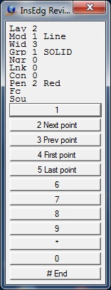
Insert Edge – Review
Review drives the cursor along an existing, user identified line.
Review Menu
|
Button |
Description |
1 |
||
2 |
Next point |
Moves cursor to the next line point |
3 |
Prev point |
Moves cursor to the previous line point |
4 |
First point |
Moves cursor to the first point on the line |
5 |
Last point |
Moves cursor to the last point on the line |
6 |
|
|
7 |
||
8 |
||
9 |
||
* |
|
|
0 |
|
|
# |
End |
Ends review and returns to the main menu |
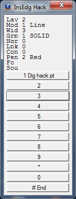
Insert Edge – Extend/hack Line
The cursor may be placed near an existing line and the closest line will be extended to or hacked at the point digitized (the hack point). If the line is to be extended the endpoint on the line will be extended along the azimuth of the last line segment. If the line is to be hacked the shortest side of the line will be hacked at a 90 degree offset from the hack point. After the hack point has been digitized and the line extended or hacked, the result may will be displayed and may be accepted or rejected before re-saving the line.
Extend/hack Menu
|
Button |
Description |
1 |
Dig hack pt |
Digitizes the hack point when extending or hacking a line |
2 |
||
3 |
||
4 |
||
5 |
||
6 |
|
|
7 |
||
8 |
||
9 |
||
* |
|
|
0 |
|
|
# |
End |
Ends Extend/hack and returns to the main menu |
Insert Edge – Join Lines
Two existing lines may be joined by placing the cursor near both lines and digitizing a point (the join point). The join point will be the common point between the two lines. Lines will be extended or hacked to the join point. After the join point has been digitized and the lines joined, the result may will be displayed and may be accepted or rejected before re-saving the lines.
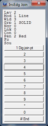
Join Lines Menu
|
Button |
Description |
1 |
Dig join pt |
Digitizes the join point when joining two lines |
2 |
||
3 |
||
4 |
||
5 |
||
6 |
|
|
7 |
||
8 |
||
9 |
||
* |
|
|
0 |
|
|
# |
End |
Ends Join Lines and returns to the main menu |
Insert Edge – Delete Line
Deletes an existing line. When a line is identified to be deleted it may be accepted or rejected before deletion.
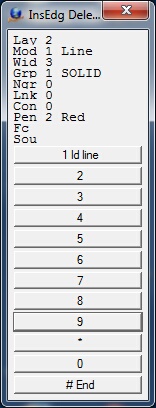
Delete Line Menu
|
Button |
Description |
1 |
Id line |
Identifies the line to delete |
2 |
||
3 |
||
4 |
||
5 |
||
6 |
|
|
7 |
||
8 |
||
9 |
||
* |
|
|
0 |
|
|
# |
End |
Ends Delete Line and returns to the main menu |
Insert Edge Parameters
The Insert Edge parameters may be defined by pressing button 7 from the Main menu.
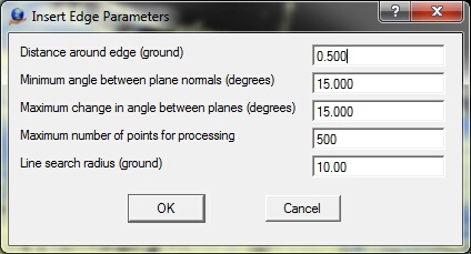
Parameters
Distance around edge (ground)
Defines a cylinder around the edge line used for processing. The planar faces of the break should extend somewhat beyond this distance. (ground, default=0.5)
Minimum angle between plain normals (degrees)
Provides a limit to how close planes on either side of the edge line are allowed to get to parallel. (degrees, default=15)
Maximum change in angle between planes (degrees)
The algorithm follows an edge line by modeling it as intersecting planes. The angle between the plane normals describes the shape of the edge. The Maximum Change parameter limits how much change in the shape will be tolerated before stopping. (degrees, default=15)
Maximum number of points for processing
The maximum number of points to use in processing a segment of an edge line. This allows the processing to remain reasonably time stable in very dense data. (default=500)
Line search radius (ground)
Search radius and endpoint extend distance when searching for lines to join or extend. (ground, default=10)
Local Commands
The following key-ins may be used to change run-time parameters. They may be keyed in, placed in macros or more commonly placed in the Local Args field in a Function Key.
Key-in |
Description |
Range |
Lay= |
Layer number |
1-32001 |
Mod= |
Mode |
1=Line 2=Spline |
Grp= |
Graphic pointer |
1-1000 |
Wid= |
Line width |
0-255 |
Pen= |
Pen number |
1-256 |
Con= |
Construction flag |
0-1 |
Ngr= |
Non graphic pointer |
32-bit |
Lnk= |
Link number |
32-bit |
Fc= |
Feature code |
15 char |
MaxDis= |
Distance around edge |
ground (default=0.5) |
MinAng= |
Minimum angle between plain normals |
degrees (default=15) |
MaxCha= |
Maximum change in angle between planes |
degrees (default=15) |
MaxPts= |
Maximum number of points for processing |
(default=500) |
LinSea= |
Line search radius |
ground (default=10) |