Vr Mapping |
ON-LINE REFERENCE DOCUMENTATION CARDINAL SYSTEMS, LLC |
Insert Road (InsRoa)
Type: Interactive/Batch Application
Inserts up to 9 parallel lines with real-time, user-determined offsets from a digitized base line.
Detailed Description
The offset lines are displayed in real-time as a base line is digitized. The distance from the base line to the offset line(s) may be chosen manually through point digitization. The elevation (Z) offset from each digitized point along the base line to the point on the offset line may be determined by a digitized point or by a user defined Z offset.
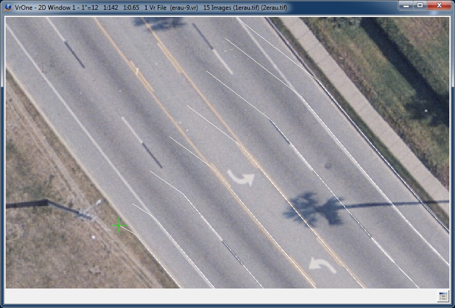
An example of digitizing eight lines.
In the example above, seven lines are being offset from a digitized base line (shown with a green cross). The cursor is shown off the intended road edge to highlight the interactive display of the base line and offset lines during the collection process.
Button Assignments
Insert Road – Start
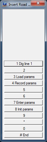
The Insert Road Start dialog
When Insert Road starts, initial points for the base line and offset lines need to be digitized. These initial points provide the XY offset (and, if specified, Z offset). Even if a line's XYZ offset is defined, the initial point on the offset line must be digitized.
|
Button |
Description |
1 |
Dig line n |
Identifies the initial line point to digitize (n= 1-number of lines specified in parameters) |
2 |
||
3 |
Load params |
Loads an Insert Road parameter file. |
4 |
Save params |
Saves current parameters as an Insert Road parameter file with a user- defined file name |
5 |
|
|
6 |
|
|
7 |
Enter params |
Enter/edit Insert Road parameters (see Insert Road Parameters) |
8 |
Init params |
Initializes the Insert Road parameters |
9 |
|
|
* |
|
|
0 |
|
|
# |
End |
Ends application |
Insert Road – Main
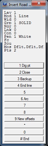
The Insert Road Main dialog
After the initial offset points have been digitized, points along the base line may be digitized. The corresponding points along the user defined offset lines will be computed and displayed in real-time. This menu will remain active until "New offsets" or "End" is selected. When lines have been saved by pressing the "End line" button, new lines may be digitized using the current line offset parameters.
|
Button |
Description |
1 |
Dig pt |
Digitize point on base line |
2 |
Close |
Closes the current line but does not save the line |
3 |
Backup |
Deletes the last pint on the current line |
4 |
End line |
Ends and saves the base line and offset lines |
5 |
|
|
6 |
Arc |
Fits an arc through the last three line points on the base line and the offset line |
7 |
||
8 |
New offsets |
Allows new line offsets to be digitized by returning to the Start menu |
9 |
|
|
* |
|
|
0 |
|
|
# |
End |
Ends application |
Insert Road Parameters

The Insert Road parameter dialog
The Insert Road parameters may be defined by pressing button 7 on the startup Menu Keys. The list box on the far left displays the currently active lines. Selecting a line number allows the entry/edit of the parameters for that line. The first line is always the base line.
Number of lines (including base line)
Specifies the number of lines to place (including the base line).
Line name
Defines the name of each line for user reference. This name is not stored with the line entity.
Layer for line
Specifies the layer into which to place each line. If the layer number is set to -1 for any of the offset lines, the base line's layer is used. Layer number ranges from 1 to 32,000.
Graphic pointer for line
Specifies graphic pointer to use for each line. If the graphic pointer is set to -1 for any of the offset lines, the graphic pointer of the base line is used.
Line Xy offset mode
Determines the method by which the current line's XY offset is set. Options are:
| • | Use digitized Xy offset: Uses the distance from the first digitized base line point to the first digitized point on the offset line. |
| • | Use line Xy offset: Uses the value in the "Line Xy offset" field. |
Line Xy offset
Defines in ground units the XY offset of the line from the baseline if f "Line Xy offset mode" is set to "Use Line Xy offset".
Line Z offset mode
Specifies how the z offset distance is set for the current line. Options are:
| • | Use digitized Z offset: Uses the elevation difference from the first digitized base line point to the first digitized point on the offset line. |
| • | Use Line Z offset: Uses the value in the "Line Z offset" field. |
Line Z offset
Defines in ground units the Z offset of the line from the baseline if "Line Z offset mode" is set to "Use Line Z offset".