Vr Mapping |
ON-LINE REFERENCE DOCUMENTATION CARDINAL SYSTEMS, LLC |
Insert Fly Line (InsFly)
Type: Interactive Application
Digitizes a line in fly mode, in which the line is drawn freehand in stream mode. Places the proper number of points on the line as determined by user parameters to make the line smooth. This is useful for digitizing contours, water lines and DTM break lines. A manual mode, which allows points to be digitized manually, may be engaged when in stream digitizing mode.
Both the VrOne key layout and the old style key layout are supported. The key layout may be set in Enter Parameters from the Main Menu.
Local Commands
Key-in |
Description |
Range |
LAY= |
Layer number |
1 – 10001 |
MOD= |
Mode |
1 = Line 2 = Spline |
GRP= |
Graphic pointer |
1 – 60 |
WID= |
Width |
0 – 255 |
PEN= |
Pen number |
1 – 256 |
CON= |
Construction flag |
0 – 1 |
NGR= |
Non graphic pointer |
32 bit |
LNK= |
Link number |
32 bit |
FC= |
Feature code |
15 characters |
DIG= |
Digitized point at location specified |
X Y Z |
FKEY= |
Change to function key properties |
Function Key Name |
TUBRAD= |
X,y tube radius |
Inches | Mm |
MAXDIS= |
Maximum tube distance |
Inches | Mm |
DITDIS= |
Dither distance |
Inches | Mm |
ZTUB= |
Z tube radius |
Ground value 0 = Disabled |
DITBUF= |
Maximum dither point buffer size |
100-10,000 |
LAKLIN= |
Makes Lake Line in which all the elevations on the line are the same as the first point. |
0=Off 1=On |
KEYLAY= |
Key layout |
0=Normal 1=Old style |
PARAMETERS
Tube Filter
When filtering lines, two parameters determine which points are kept:
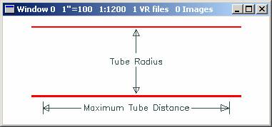
When a data point falls outside the current tube, the last point within the tube is saved and a new tube direction is set based on the new point and the last point. If a line is straight and points do not move out of the tube, the Maximum tube distance is used to save points.
When setting these parameters, the Maximum tube distance should always be larger than the Tube radius.
Example:
Tube radius |
02 inches or 0.5 mm |
Maximum tube distance |
0.5 inches or 12 mm |
Dither Distance
When collecting a line, all the points are first placed in a buffer. When the line is ended the points are then filtered using the current parameters. The Dither distance specifies how far the floating mark or cursor must travel before a point is placed in the buffer.
Example:
Dither distance: .05 inches or 1.3 mm
Z Rube Radius
Specifies in ground units the elevation filter to apply to points in the input buffer. If set to 0, no elevation filter is applied.
When a line is being collected, points are stored in a temporary buffer using the Dither Distance. When the line is saved, the points in the buffer are filtered using the Tube Radius, Z Tube Radius and Maximum Distance. Points that are “Forced” during collection pass through the filter unmodified.
Dither Buffer Size
This parameter defines the maximum number of points that may be stored in the dither buffer. When this buffer is full, the points are filtered and the resulting line is saved. If the line is not yet complete input will continue seamlessly. Setting the dither buffer size to a smaller value will typically produce multiple lines that make up the entire line. The interactive application Join Lines (JoiLin) or the batch application Batch Join (BatJoi) may be used to join the multiple lines into a single line. The default value for the dither buffer size is 10,000.
Button Assignments
Ins Fly Line – Main
|
Button |
Description |
1 |
Start |
Starts the line. |
2 |
Z + |
Increments the current elevation by the contour interval. |
3 |
Z - |
Decrements the current elevation by the contour interval. |
4 |
Z Round |
Rounds the current elevation to the nearest contour interval. |
5 |
|
|
6 |
|
|
7 |
Enter Params |
Enter parameters from dialog box. |
8 |
|
|
9 |
|
|
* |
|
|
0 |
Toggle Snap |
Toggles snap on/off. |
# |
End |
Ends Edit Line. |
The contour interval may be set in Z Source (Zsou).
Ins Fly Line – Stream (VrOne layout)
|
Button |
Description |
1 |
Force |
Forces a point into the buffer. |
2 |
Close |
Closes and saves the current line. |
3 |
Backup |
Backs up one point and drives the instrument to that point if possible. |
4 |
End line |
Ends and saves the current fly line. |
5 |
Dig manual |
Allows manual point digitization. |
6 |
Splice/Pause |
Starts Splice menu. |
7 |
|
|
8 |
|
|
9 |
|
|
* |
|
|
0 |
Toggle Snap |
Starts Snap menu. |
# |
End |
Ends Edit Line. |
Ins Fly Line – Stream (Old style layout)
|
Button |
Description |
1 |
End line |
Ends and saves the current fly line. |
2 |
Close |
Closes and saves the current line. |
3 |
Backup |
Backs up one point and drives the instrument to that point if possible. |
4 |
Force |
Forces a point into the buffer. |
5 |
Dig manual |
Allows manual point digitization. |
6 |
Splice/Pause |
Starts Splice menu. |
7 |
|
|
8 |
|
|
9 |
|
|
* |
|
|
0 |
Toggle Snap |
Starts Snap menu. |
# |
End |
Ends Edit Line. |
Ins Fly Line – Splice (VrOne layout)
When this menu is entered, point collection stops and the operator may look around. This is often used when pulling contours or break-lines through dense vegetation. Splice may be used to remove the end portion of the line and continue from that point.
|
Button |
Description |
1 |
Force |
Forces a point into the buffer. |
2 |
Resume |
Resumes line collection. |
3 |
Splice |
Digitizes the splice point. The line from this point to the end of the line will be erased, the instrument will be driven to the closest point on the current line, and digitizing will resume. |
4 |
End line |
Ends and saves the line. |
5 |
|
|
6 |
|
|
7 |
|
|
8 |
|
|
9 |
|
|
* |
|
|
0 |
Toggle Snap |
Toggles snap on/off. |
# |
End |
Ends Edit Line. |
Ins Fly Line – Splice (Old style layout)
When this menu is entered, point collection stops and the operator may look around. This is often used when pulling contours or break-lines through dense vegetation. Splice may be used to remove the end portion of the line and continue from that point.
|
Button |
Description |
1 |
Splice |
Digitizes the splice point. The line from this point to the end of the line will be erased, the instrument will be driven to the closest point on the current line, and digitizing will resume. |
2 |
Resume |
Resumes line collection. |
3 |
End line |
Ends and saves the line. |
4 |
Force |
Forces a point into the buffer. |
5 |
|
|
6 |
|
|
7 |
|
|
8 |
|
|
9 |
|
|
* |
|
|
0 |
Toggle Snap |
Toggles snap on/off. |
# |
End |
Ends Edit Line. |
Ins Fly Line – Snap
This menu will be used if snap is turned on from the Stream menu. It is a modified version of snap that allows snapping and ending a line. Due to the nature of Fly Line, snapping to end a line requires this menu.
|
Button |
Description |
1 |
Snap and End |
Snaps and ends the line. |
2 |
Resume |
Resumes line by returning to the Stream menu. |
3 |
|
|
4 |
|
|
5 |
|
|
6 |
|
|
7 |
|
|
8 |
|
|
9 |
|
|
* |
|
|
0 |
|
|
# |
|
|
Ins Fly Line – Dig Manual
Points may be digitized manually when button 5 is pressed when in Stream mode.
|
Button |
Description |
1 |
Dig point |
Digitizes a new point. |
2 |
Resume |
Resumes stream digitizing. |
3 |
|
|
4 |
End line |
Ends and saves the current line. |
5 |
|
|
6 |
|
|
7 |
|
|
8 |
|
|
9 |
|
|
* |
|
|
0 |
|
|
# |
Resume |
Resumes stream digitizing. |