Vr Mapping |
ON-LINE REFERENCE DOCUMENTATION CARDINAL SYSTEMS, LLC |
Insert Orthogonal Corner (InsOrc)
Type: Interactive Application
Inserts an orthogonal line which results in a squared polygon based on the first two points read and subsequent polygon corner points. The line may be closed back to the original line segment or left open. Each squared polygon is started by reading two corner points along one side of the polygon. This is normally the longest or most visible side. Subsequent points are read on polygon corners. The polygon must be read in a clockwise or counterclockwise direction from the base line.
A Squaring Tolerance may be specified. If the next corner point is within this tolerance the resulting line will be orthogonal to the original line segment. If the next corner point is outside this tolerance then the line point will fall where digitized resulting in an un-squared side. Each corner point my turn 0, 90, 180 or 270 degrees from the previous segment. If a corner point is 0 degrees from the previous line segment then the new line will be a straight line from the previous line.
While digitizing, a rubber-banded line will show the direction and location of the next point. If the current cursor position is within the Squaring Tolerance then the line will be shown orthogonal to the first line on the polygon.
There are three polygon squaring applications in Vr. See Insert Square Line (InsSqu) and Insert Orthogonal Line (InsOrt) for more information about the other two available polygon squaring applications.
Local Commands
Key-in |
Description |
Range |
LAY= |
Layer number |
1-10001 |
MOD= |
Mode |
1=Line 2=Spline |
GRP= |
Graphic pointer |
1-60 |
WID= |
Line width |
0-255 |
PEN= |
Pen number |
1-256 |
CON= |
Construction flag |
0-1 |
NGR= |
Non graphic pointer |
32 bit |
LNK= |
Link number |
32 bit |
FC= |
Feature code |
15 char |
DIG=x y z |
Digitizes point |
X Y Z |
FKEY=name |
Changes to function key parameters |
Function key name |
SQUTOL= |
Sets the Squaring Tolerance |
5 - 40 degrees |
Button Assignments
Ins Orthog Cor - Main
Button |
Description |
1 Dig |
corner 1 – Digitize the first corner point of the base line. corner 2 – Digitize the second corner point of the base line. corner – Digitize a point on the next polygon corner. |
2 Close |
Closes the polygon to the first vertex and saves. |
3 Backup |
Deletes the last point on the current line. |
4 End |
Ends and saves the current line without closing. |
5 |
|
6 |
|
7 |
|
8 |
|
9 |
|
* Menu board |
Makes selection from Menu Board. |
0 Toggle snap |
Toggles snapping on / off. |
# End |
Ends Insert Orthogonal Corner. |
Point Measurement Sequence
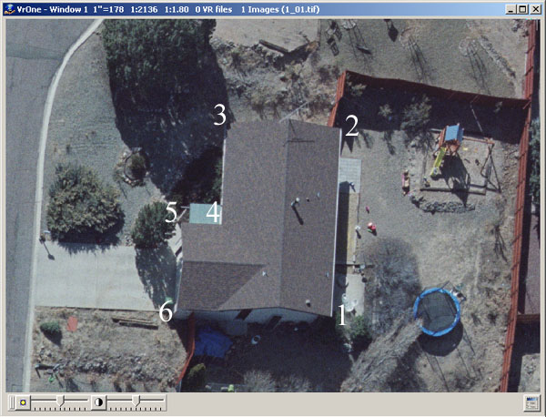
Points 1 and 2 define the base line and are read on the corners' longest side in this example. These points establish the azimuth of the squared polygon. Points 3 through 6 are observed on subsequent polygon corners. The polygon may be read in clockwise or counterclockwise direction and corners must be read in sequential order. After point 6 has been read the polygon may be closed.
NOTE: When closing a polygon, the last point observed (point 6 in this case) is adjusted to be orthogonal with the first point observed if it is within the Squaring Tolerance.
Vr Button Presses

The observation of the base line and the subsequent polygon corners are made with the Vr button 1. To close the polygon after the final line corner has been observed, Vr button 2 is pressed. Note the last line corner must be observed before Vr button 2 can be pressed. To leave a polygon open, Vr button 4 may be pressed.