Vr Mapping |
ON-LINE REFERENCE DOCUMENTATION CARDINAL SYSTEMS, LLC |
Make Polygons (MakPol)
Type: Batch Application
Makes closed polygons using existing line segments and centroids.
Detailed Description
Make Polygons looks at the spatial relationship of existing line segments and creates enclosing polygons around areas containing centroid symbols. Lines can be collected in any direction, but they must be noded and broken into segments before running Make Polygon. Make polygon first looks for all lines in the user specified feature layers and forms all possible polygon areas from these lines. A polygon is retained only if it has a centroid symbol on the interior. The resulting polygons are placed in user specified layers, along with polygons that represent any holes that were found within the main polygons. A drive file is created so the user can examine any centroids that were not enclosed by a polygon, and also any areas that have more than one centroid. Several centroid layers may be searched for at once. Each layer of centroids will have its own polygon save layer.
Basic steps for using Make Polygons
| • | Collect data normally. Undershoots and overlaps are allowed as long as they are within tolerance used in Batch Trim. |
| • | Place centroid symbols (any symbol of choice) inside each closed area. Use a unique layer for each area type (driveways, sidewalks, etc.). |
| • | After all data is collected, run Batch Trim to handle any undershoots or overlaps. |
| • | Make a copy of the file and work on the copy for the remaining steps. This is necessary because the batch node and break will break the original lines into segments at all node locations. |
| • | Run Batch Node and choose the "Node and Break" option. It will be necessary to specify the same layers that will be involved in the Make Polygon process. One requirement of Make Polygon is that all crossing lines are broken at the intersection points. |
| • | Run Make Polygons. |
Before attempting to use this on a large scale project, testing on a small subset of data is recommended to make sure the processing steps are correct and the results are as expected.
Make Polygons Tutorial
The video tutorial below demonstrates using Make Polygons on a small sample data set. This is best viewed with the browser in full screen mode (F11 in most browsers).
Local Commands
None
Parameters
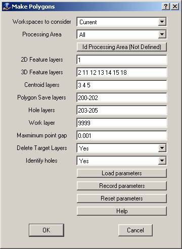
Workspaces to consider
Determines if entities in all workspaces will be considered or only those in the active workspace.
Processing Area
If ‘All’ is chosen, the entire file will be processed. If ‘User defined area’ is chosen, only lines that fall completely within a user-defined area will be processed. The user area is defined by using the button below this prompt to select an existing closed VrOne line. This is useful for troubleshooting a small area of a file without having to run the full process. By combining this with the Delete target layers option, it is possible to rerun a small area as many times as needed to ensure the polygons are correct (only target layers within the user-defined area are deleted).
Id Processing Area
Selects a line from any currently open VrOne workspace. Once a line has been selected, it will be used if “User-Defined Area” is selected for the Processing Area option. The button label will change to indicate whether a user-defined area has been selected or not. NOTE: Just selecting a user-defined area does not mean it will be used. The Processing Area option must also be set to “User-Defined Area”.
2D Feature layers
Layers containing features that do not contain valid elevations on the line points. If creating polygons of all parking lots, then this would contain features such as buildings or sheet cut lines that were not collected with a ground elevation. The points along the resulting polygons that are taken from features in these layers will contain interpolated elevations based on the main search line.
3D Feature layers
Layers containing features that do contain valid elevations on the line points. If creating polygons of all parking lots, then this would contain features such as road edges that were collected with a ground elevation. The points along the resulting polygons that are taken from features in these layers will contain the original elevation value of the feature.
Centroid layers
Layers containing the centroids. This can be any valid layer number line. Any symbol found on these layers will be considered a centroid. The location of centroids that do not fall within a polygon will be written to the error drive file. The location of any duplicate centroids within a single polygon will be written to the error drive file.
Polygon Save layers
The final closed polygons will be placed in this layer. This can be any valid layer number line, but it is essential to have the same number of save layers as centroid layers. Each save layer corresponds to a centroid layer.
Example: Layers "3 4" are specified for the Centroid Layers, and layers "200 201" are specified for the save layers. All polygons associated with centroids on layer 3 will be placed on layer 200, and all polygons associated with centroids on layer 4 will be placed in layer 201. Number ranges may also be used. For example: Centroid layers: 3 4 5, and Save layers 200-203.
Hole layers
Polygons that do not contain centroids and are found inside the main polygons will be stored in this layer in a counterclockwise direction. This can be any valid layer number line, but must have the same number hole layers as polygon save layers. Each hole layer corresponds to a save layer.
Example: Layers "200 201" are specified for the save layers, and layers "210 211" are specified for the hole layers. All holes inside polygons on layer 200 will be placed on layer 210, and all holes inside polygons on layer 201 will be placed in layer 211. umber ranges may also be used.
Work layer
This layer will be used to store temporary lines during the polygon generation process. All existing entities in this layer will be deleted when Make Polygon starts, and the layer will be left empty when Make Polygon has finished.
Maximum point gap
This allows the user to specify a tolerance to handle rounding errors between endpoints. Normally, this value can be left at it’s default value (0.0001), but it may be necessary to make it larger if some polygons are not being found because endpoints do not match up exactly. Do not set this value too high or it can find false point matches.
Delete Target Layers
If set to Yes, all entities on the Polygon Save Layers and Hole Layers will be deleted before processing begins.
Identify holes
If set to Yes, polygon holes will be flagged and placed in the Hole layers. If set to No, only the main Polygons will be saved to the Polygon save layers. When processing a file for the first time, if it is anticipated that there will be some cleanup, this may be turned off to save time. After any problem areas have been fixed, it may be turned on for the final run. On a clean file, this step usually doesn't take too long. Iff dealing with an unclean dataset that is making large polygon regions, a large number of holes may be flagged, leading to a longer run time. If it is noticed that the Identify holes step (last step in the process) is taking a long time, it may be because large invalid polygon regions are being generated.
Examples
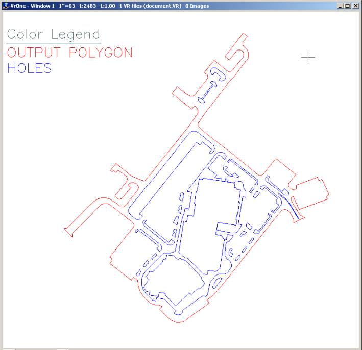
This example shows a typical parking lot area with internal islands and outside attachments to road edges and buildings.
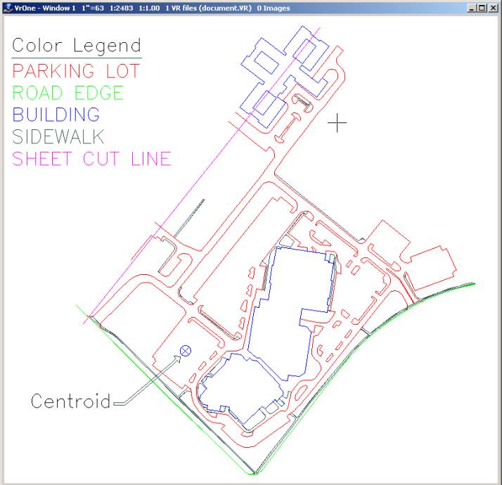
This is the result of running Make Polygon on the above data.