Vr Mapping |
ON-LINE REFERENCE DOCUMENTATION CARDINAL SYSTEMS, LLC |
Vr Camera Calibration (CamCal)
Setting Up and Taking Calibration Photos
The Vr Camera Calibration is a stand-alone program to perform camera lens calibrations. The parameters output from this process include the camera's aspect ratio, focal length, principal point, scale factor and lens distortion (pin-cushion effect). The calibration method used by this program uses photographs taken of a calibration grid from different angles. This method is refereed to as Bouguet's Method.
NOTE: The Vr Camera Calibration (CamCal) program is not yet released. At the present time camera calibration photos may be sent to Cardinal Systems for processing. Contact Cardinal Systems for more information. (07-Jan-2015)
Camera calibration is an important first step when preparing to extract measurements from images. The process of camera calibration is relating the ideal model of that camera to the actual physical device. Information about the camera must be known in order to make accurate measurements. This information includes aspect ratio, focal length, principal point, scale factor and lens distortion (pin-cushion effect).
The U.S. Geological Survey (USGS) has provided high accuracy camera calibration services for aerial cameras for many years and continues to do so today. Over the years the USGS Report of Calibration from the Optical Science Laboratory at USGS has become the defacto requirement of other U.S. Federal agencies, as well as State and local governments. The USGS Report of Calibration defines the math model an an example of how to use the parameters given.
With the increased use of small format and handheld cameras for aerial and non-aerial mapping and measurements the need to calibrate lower cost cameras became necessary. Out of this need came the Vr Camera Calibration (CamCal) program. The calibration method used by this program uses photographs taken of a calibration grid from different angles. This method was made popular by Jean-Yves Bouguet and in his "Camera Calibration Toolbox for Matlab" work and this method, which is used by CamCal, is referred to as Bouguet's Method.
The USGS camera calibration is computed using the Simultaneous Multiframe Analytical Calibration system (SMAC model) and the parameters output by this method are supported by the Vr Camera Calibration program. This allows the output from CamCal to be supported by existing photogrammetric work flows.
In theory, it is possible to define a lens that will have no distortions. In practice, however there is no such lens. All lenses have some amount of distortion and this distortion is classified as either pincushion or barrel distortion.
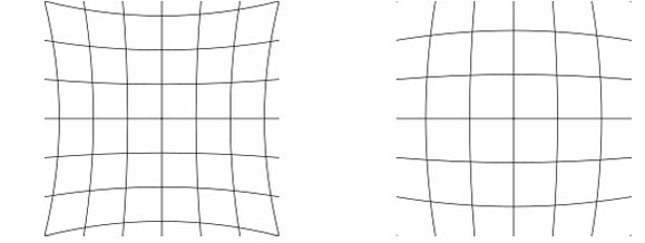
Pincusion and barrel distortion
A simple example of barrel lens distortion is apparent when you take an image of an object with straight vertical or horizontal lines and the lines appear curved in the image. This “barrel” or “fish-eye” effect and is more apparent on lenses with shorter focal lengths. The example below was taken using a fish-eye lens that would not be used for accurate mapping even after calibration but highlights the barrel effect.
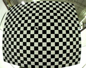 Uncorrected image |
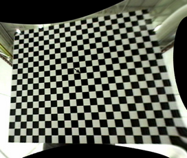 Corrected image |
In a stereo model where both images are uncorrected and a barrel effect lens distortion condition exists, the resulting stereo model will have a 3-dimensional dome distortion resulting in inaccurate measurements. The example below shows two stereo models taken with a GoPro camera with a 3mm fish-eye lens. The blue lines represent a stereo model in which the images were partially corrected in order to obtain stereo and the yellow lines represent a stereo model using a camera calibration from CamCal. The Z has been exaggerated in this example to highlight the effect of lens distortion on a stereo model.
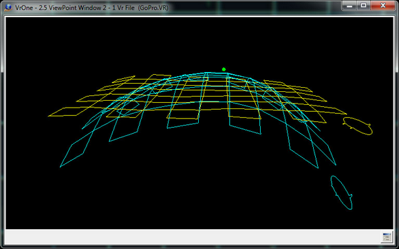
Lens distortion effects on stereo mode (blue) and the correction of the distortions (yellow)
Setting Up and Taking Calibration Photos
The calibration grid (chessboard or checker board) pattern should be asymmetric and consist of even and odd dimensions (i.e. 24x19). Using an even-odd asymmetry yields a calibration grid that has only one symmetry axis, so the calibration grid orientation can always be identified uniquely.
When printing the calibration grid, make sure the printer does not rescale the document which is where the x axis has a different scale than the y axis. Failure to do so will cause intrinsic parameters to be off by a scale-factor. Measure with a ruler to make sure the board has an aspect ratio of 1:1.
The calibration grid needs to be mounted on a flat surface and any warping will decrease calibration accuracy. An ideal surface will be rigid and smooth, for example a table, glass, or marble tile. Cardboard or foam will still work well, but has a tendency to warp over time. It is not necessary, however, to try to make a perfectly smooth surface for the calibration grid.
A calibration grid with more grid squares is advantageous. For example, it's possible to use a calibration grid with dimensions of 9x6 as shown in the examples below but a calibration grid with dimensions such as 23x18 is preferred.
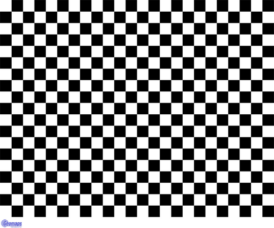
23x18 calibration grid (courtesy of Geomaps International, Inc.)
The calibration grid show above can be downloaded as a PDF file at Camera Calibration Board 23x18.
A lower resolution board may be used if focusing is an issue and can be downloaded at Camera Calibration Board 16x09.
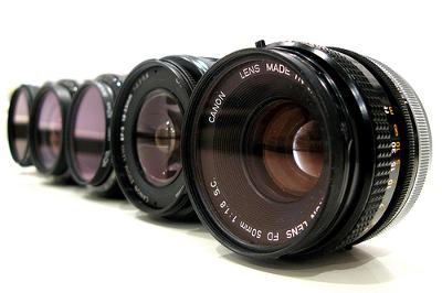
The camera should have a fixed focal length and zoom lenses should be avoided. The calibration procedure assumes that every photo taken has the same focal length. Many scientific cameras have a fixed focal length so this is not an issue. Using a tripod to stabilize the camera is also a good idea but not required. Image motion and being out of focus will make it more difficult for the software to find the grid intersections on the calibration grid. To minimize image motion, use a flash if possible or take the photos in a well lighted area. Also select the highest possible lens f-stop to obtain a better depth of field when taking oblique photos. Typical single lens reflex cameras support f-stops up to f/22.
Taking a diverse set of in focus photos are essential to calibration. Photos should be taken at various different orientations (or views), distances, and locations in the photo, while filling up as much of the photo as possible. The entire board must be in the photos and all the corners must be able to be found by the calibration software.
Be sure that the calibration grid appears along the photo edge and the center. If all the pictures are taken in one region then the results will be biased, even if the residual error is low. The whole calibration grid needs to be visible in the photo and in some cases the calibration grid's border also needs to be visible. Also, even though oblique angle views are required, avoid extreme angles or distances when taking the photos.
Along with normally orientated camera rotation, photos taken with a 90 degree rotation are required. This cam be accomplished by rotating the camera or the calibration grid sideways.
When taking the camera calibration photos, the following points should be considered.
| • | The entire calibration grid must be contained within each photo |
| • | Fill the field of view as much as possible. |
| • | Oblique views are more important than nadir views. |
| • | Photos showing the calibration grid at a 90 degree rotation is required. |
| • | Try to fill the photo corners and edges as best as possible. |
| • | Vary the camera distance to the calibration grid. |
| • | It's better to take too many photos rather than too few. 30 to 40 photos are a reasonable amount. |
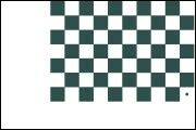
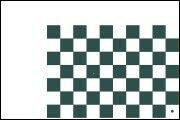
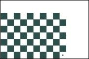
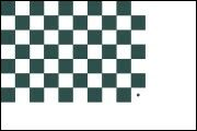
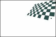
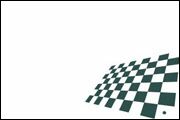
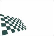
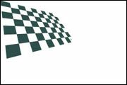
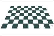
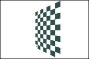
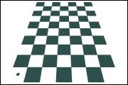
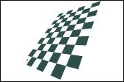
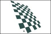
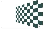
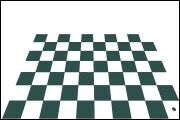
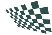
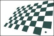
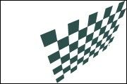
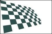
Photos should be taken from multiple angles or views. A total of nine views for each camera or calibration grid rotation should be taken as follows. Following are examples showing the nine views from the un-rotated orientation.
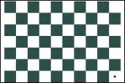 Nadir |
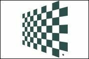 Right |
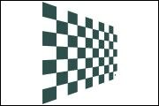 Left |
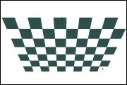 Up |
 Up Right |
 Up Left |
 Down |
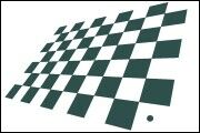 Down Right |
 Down Left |
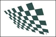
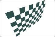
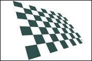
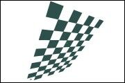
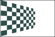
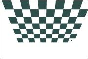
Following are examples showing the nine views from the 90 degree rotation orientation. Either the camera or the calibration grid is rotated 90 degrees clockwise or counterclockwise. In the examples below, the calibration grid was rotated 90 degrees clockwise.
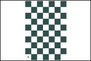 Nadir |
 Right |
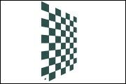 Left |
 Up |
 Up Right |
 Up Left |
 Down |
 Down Right |
 Down Left |
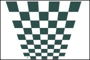
It's best to fill as much of the photo frame as possible while keeping the entire calibration grid in the frame. The edges and corners are important. Filling the frame and positioning the calibration grid near the corners and edges is easy for the nadir views but becomes more difficult from the oblique views. More than one photo per view might be required to meet this criteria from the oblique views. Following are some examples.
|
|
|
|
|
|
|
|
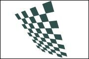
In situations where the scale of the calibration grid does not fill the frame, it is advantageous to take multiple photos of the same view, placing the calibration grid in the corners as best as possible. Following are some examples.
|
|
|
|
|
|
|
|