Vr Mapping |
ON-LINE REFERENCE DOCUMENTATION CARDINAL SYSTEMS, LLC |
DXF IN (DxfIn)
Type: Translator
Translates DXF (Drawing Exchange Format) files to VrOne files.
The DXF format is commonly used to translate map data to Autodesk’s AutoCAD program. Due to the popularity of the format, it is used by many other CADD and GIS (Geographic Information Systems) systems for the transfer of map vector data. From GIS to civil engineering systems, DXF is considered the de-facto standard for moving vector data. Experience has shown that DXF is well suited to move vector data to the ARC INFO GIS system.
The DXF IN translator is limited to those AutoCAD entities that have a meaningful equivalent in VrOne. The following table describes the AutoCAD entities that are translated into VrOne from a DXF file.
AutoCAD Entity |
VrOne Entity |
Line |
Line |
3D Line |
Line |
Polyline (2D or 3D) |
Line |
Solid |
Line |
0 length line |
Symbol |
Point |
Symbol |
Block |
Symbol |
Shape |
Symbol |
Circle |
Line with arc codes |
Arc |
Line with arc codes |
Dimension |
Exploded into multiple entities |
Text |
Text |
AutoCAD is a registered trademark of Autodesk Inc.
|
|
Available Key-ins
Key-in |
Description |
Range |
PARFIL= |
Load parameter file |
Dxf In parameter file name (.dxi) |
HELP |
Display help |
|
RUN |
Run Dxf In |
|
DXF In
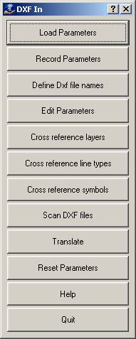
Loads previously recorded DXF In (.dxi) parameter file.
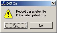
Records current translation parameters to a DXF In (.dxi) parameter file.
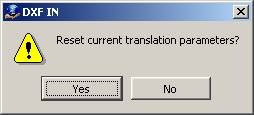
Resets translation parameters to default values. NOTE: Current translation parameters will be lost.
Allows one or more DXF files to be selected for translation.
Allows editing general translation parameters.
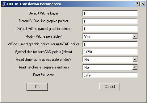
Default VrOne Layer
Specifies default layer to place entities that are not cross-referenced.
Default VrOne line graphic pointer
Specifies default graphic pointer to use on lines that are not cross-referenced.
Default VrOne symbol graphic pointer
Specifies default graphic pointer to use on symbols that are not cross-referenced.
Modify VrOne pen table?
Specifies whether the VrOne pen table is modified to match the colors defined in the DXF file layer table.
VrOne symbol graphic pointer for AutoCAD points
Specifieshe graphics pointer to use when translating AutoCAD points or AutoCAD 0 length lines to VrOne symbols.
Symbol size for AutoCAD points (in|mm)
Defines in display units symbol size to use when translating AutoCAD points or AutoCAD 0 length lines to VrOne symbols.
Read dimensions as separate entities?
VrOne does not have an equivalent to the AutoCAD dimension entity. Normally, dimension entities are ignored, but if this is set to yes, the individual entities that make up the dimension entity are translated as separate VrOne entities. All standard translation parameters are applied to the separate entities.
Read hatches as separate entities?
VrOne does not have an equivalent to the AutoCAD hatch entity. Normally, hatch entities are ignored, but if this is set to yes, the individual entities that make up the hatch entity are translated as separate VrOne entities. All standard translation parameters are applied to the separate entities.
Error file name
Any problems encountered during translation are included in this file.
AutoCAD uses a layer table to defines layer names. Within each layer, a line type and color is defined. VrOne uses layer numbers and has 10,001 predefined layers.
This dialog allows the AutoCAD layer names to be cross-referenced to VrOne layer numbers. Each layer name may be up to 32 characters in length.
While it is possible to name layers in VrOne, the names are only for user reference and VrOne handles all layers by number.
An easy way to define this table is supplied by using the “Scan DXF files” option. This scans a list of DXF file and creates a layer table entry for each layer used. NOTE: If layer names have been defined in VrOne, those layer names will be used in the table. If a layer name has not been defined in VrOne, the layer number will be used with the word “Layer” before the number.
Each individual entity in the DXF file may have its color and linetype assigned based on the layer table settings (this is called BYLAYER in AutoCAD) or it may have a specific value set for the color and linetype. If an entity uses BYLAYER for color or linetype, the linetype or color defined in the layer table is used. The resulting linetype is then cross-referenced to the line types table defined in the next section.
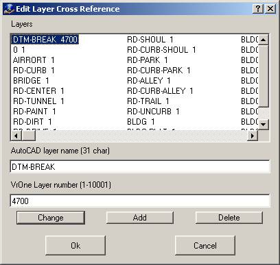
AutoCAD layer name (31 char)
Specifies the input layer name from the DXF file.
VrOne layer number (1-10001)
Specifies the VrOne output layer number.
AutoCAD uses names to define linetypes (line fonts). VrOne uses graphic pointer numbers to define line fonts. Although names are assigned to VrOne line fonts, the graphic pointer number is the primary means for identifying line fonts in VrOne. This table allows the AutoCAD linetype names to be cross-referenced to VrOne line font graphic pointer numbers. See the cross-reference layers section for an explanation of how the layer table in the DXF file relates to this cross-reference table.
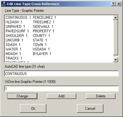
AutoCAD line type (31 char)
Defines the input linetype name from the DXF file.
VrOne line Graphic Pointer (1-10001)
Specifies the VrOne output line font graphic pointer.
AutoCAD uses names to define blocks (symbols). VrOne uses graphic pointer numbers to define symbols. Although names are assigned to VrOne symbols, the graphic pointer number is the primary method for identifying symbols in VrOne. This table allows the AutoCAD block names to be cross-referenced to VrOne symbol graphic pointer numbers.
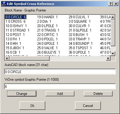
AutoCAD block name (31 char)
Defines the input block name from the DXF file.
VrOne symbol Graphic Pointer (1-10001)
Specifies the VrOne output symbol graphic pointer.
Scans one or more DXF files and places entries in the cross-reference tables for all layers, linetypes, and symbols found. This should be used as a starting point for populating the cross-reference tables. Default output values are written that can be edited to match translation needs. The “Define Dxf file names” option must be used before this will run.
The following options are displayed before the DXF files are scanned:

Scan ENTITIES section only
If set to yes, only the ENTITIES section of the DXF is processed. The LAYER and BLOCK definition tables are skipped, resulting in the cross-reference table only containing entries from entities that exist in the DXF file. If set to no, then all entries in the LAYER and BLOCK definition tables from the DXF file are placed in the cross-reference tables, even if there are no actual entities in the DXF file that use those layers or block definitions.
Place results in cross-reference tables
If set to no, results will only be written to the scan results file.
File name for scan results
Defines file name to which a summary of the results from scanning the DXF files is written.
Translates the currently defined DXF files to the current VrOne file.
Help
Starts the browser and displays the current help document.
Quit
Quits Dxf In and gives an option to save the current parameters.
The following steps allow one to translate DXF files into VrOne in the fewest possible steps. The result is a translation in which all lines are translated as solid, all blocks are translated as graphics pointer 1, and all entities are placed on layer 1.
| 1. | Select “Reset Parameters” |
| 2. | Select “Define Dxf file names” and select one or more DXF files. |
| 3. | Select “Scan DXF files” |
| 4. | Select “Translate” |