Vr Mapping |
ON-LINE REFERENCE DOCUMENTATION CARDINAL SYSTEMS, LLC |
Importing a Datumate Project Into Vr Aerial Triangulation (VrAirTrig)
This document explains the work flow for importing data from Datumate into VrAirTrig.
This workflow allows the import of the Datumate control point coordinates and associated measured photo coordinates along with the automatically generated tie points to be imported into VrAirTrig. After the import of the data the VrAirTrig bundle adjustment is performed which generates detailed reports and allows for comprehensive weighting parameters. Output from the bundle adjustemnet includes a camera calibration and exterior orientation (EO) parameters for the orientation of stereo models using Vr Model Set (VrModSet) or the generation of orthophotos using Vr Orthophoto (VrOrtho).
Workflow
1. Open VrAirTrig and create a project File.
4. Import the Datumate camera position solution
Open Air Trig and Create a New Project File
The 'New Project' command is located in the 'Project' window on the main title bar. After choosing a file name and location the project edit/setup wizard will open.
Importing a camera file is an optional step and is not needed if a camera file already exists. For example, the Vr Camera Calibration (VrCamCal) creates camera files.
A camera file may be imported from the Camera pull-down in the main window or it may be imported from the Project Wizard. To create a new Vr camera file from the Project Wizard click on the 'New Camera' button on the 'Cameras and Photos' tab. A Camera Edit dialog will open. Click the 'Import Camera Data' button near the top left. Change the file type to 'Datumate (.ori)' (using the combo box near the bottom right).
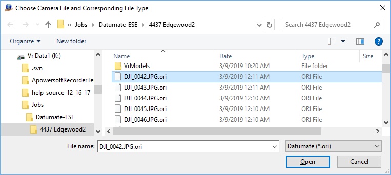
Import Camera File dialog for Datumate
The Datumate camera information is stored in the Datumate .ori files. There is a .ori file for each photo that was used by Datumate. Any .ori file may be selected if a single camera was used for the entire project. If multiple camera were used then this procedure would be repeated for each camera. If multiple cameras were used when the .ori files might need to be viewed to determine a .ori file for each camera. A fully functional camera definition will be imported, but a description can be added for convenience.
The Datumate camera import does not import radial distortions and the resulting camera file has the radial distortions turned off.
Upon clicking 'OK' to exit the camera edit window, a new camera file name may be entered in the Save Camera File and the imported camera data will be saved as a Vr camera file.
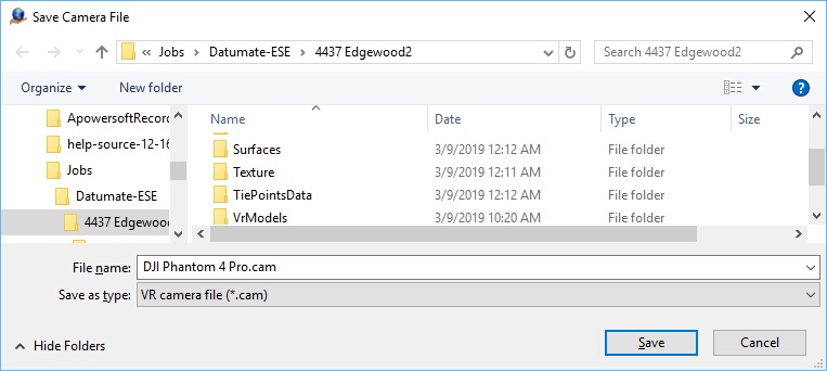
Save Camera File dialog
The new camera file name will be entered into the Project Wizard 'Camera and Photos' tab. Full documentation for the camera edit dialog is located here.
To add images to project click on the name of camera the images will be assigned to in the left table of the 'Cameras and Photos' tab of the project wizard. When a single camera is selected the 'Assign Photos to Camera' button on the bottom left becomes active. Click this button and navigate to choose the images.
On the 'Orientations and Control' tab of the project wizard the 'Control File' button is used to select ground control file. The control point data is stored in a .xml file (typically job.xml). When the control data is read and placed in a Vr control file, this file may be saved.
The Vr Mapping software adds some default header information when it saves the file.
File Example:
# Coordinate File
# Layout - Field Order Min number of fields
# 0 NAME X Y Z CX CY CZ 3
# 1 NAME Y X Z CY CX CZ 3
# 2 X Y Z NAME CX CY CZ 4
# 3 Y X Z NAME CY CX CZ 4
# 4 NAME X Y Z 3
# 5 NAME Y X Z 3
# 6 X Y Z NAME 4
# 7 Y X Z NAME 4
# 8 X Y NAME 3
# 9 Y X NAME 3
#
# Format - Coordinate format
# 0 State plane
# 1 UTM
# 2 Geographic Decimal Degrees
#
# SpZone - State plane zone
#
# Datum - Datum
# 0 NAD1927
# 1 NAD1983
#
# UtmZone - UTM Zone
# 1-60 Utm zone number
#
# Units - Coordinate units
# 0 Us Foot
# 1 International Foot
# 2 Meters
#
Layout 4
Format 0
SpZone 901
Datum 0
UtmZone 17
Units 0
#
5 1862600.861000 724626.555000 807.1600
14 1862956.537000 726104.024000 810.4900
27 1862097.709000 729995.080000 793.1600
29 1865529.981000 731805.394000 808.5700
30 1861813.412000 731226.056000 794.1000
103 1875804.906000 722601.108000 894.5390
104 1876434.487000 726668.853000 899.2450
107 1868807.915000 727037.911000 797.9120
110 1873497.612000 726632.340000 912.9600
227 1863885.554000 727376.236000 810.9500
528 1864669.954000 723806.413000 816.2600
Import the Camera Position and Orientation Solution
To import the Datumate camera positions and orientations (EOs) click on the 'Import EOs' button on the 'Orientations and Control' tab of the project wizard. A windows browse dialog will be opened. Select the Datumate file type from the combo box on the bottom right of the window (Dautmate (.ori)). Like the Datumate camera parameters, the EO data is stored in the Datumate .ori files. Since it is expected that all the .ori files are in the same folder a single .ori file is selected and all the .ori files in that folder are read.
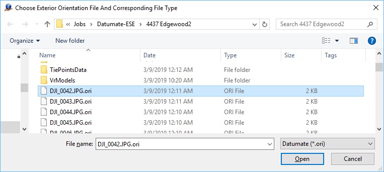
Import Exterior Orientations (EO) dialog
A message box will appear that lists how many of the images were correctly read from the input file. The entries in the table under the heading 'Exterior' will also change to 'Yes' indicating that an image has an exterior orientation (EO). See 'Import, Exterior Orientations' for more general EO importing information.
At this point, images have fully defined orientations and it can be determined if control points project into the images. The number of control points that project into each images is listed in the table under the heading 'Ctl Pts'. The entries in the table are sortable by the values in each column. To sort them by the number of control points, click on the 'Ctl Pts' header (It may be necessary to click it twice to sort the image in descending order by the number of control point). Double clicking on non-zero values in the 'Ctl Pts' column will allow you to view thumb nails of the control points in the images that they project into. Viewing some of these thumbnails is a good way to verify that the control, camera definition, and image orientations have been oriented successfully.
The Datumate image measurements are imported by selecting 'Import Measurements from the import menu on the main command ribbon.
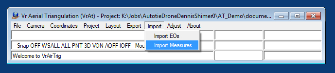
The Datumate measurements are imported from two files which are the Datumate tie points file (.txt) and the Datumate jobs file (.xml) which contains the ground control points.
Import the Tie Points
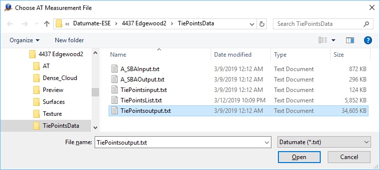
The Choose AT Measurement file dialog
The first file to import is the Datumate tie points file. This file is typically in a separate TiePointsData folder and is named TiePointsoutput.txt. The tie points are in a text file and the file type is 'Datumate (*.txt)'. Navigate to the tie points folder and select the tie points file.
Next, a dialog will be displayed which allow the setting of the At Measurement Import Parameters.
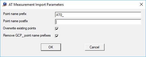
The AT Measurement Import Parameters
Point name prefix - Optionally add a prefix to all NON CONTROL point names. For this reason it is essential to define the control point file before running this import. Adding the default "AT0_" to the point names causes the software to see the imported points as automatic tie points. Automatic tie points can be winnowed, deleted, etc. more easily than points that the software believes are manual measurements.
Point name postfix - Optional post fix to all NON CONTROL point names. For this reason it is essential to define the control point file before running this import.
Overwrite existing points - If checked all previous image points will be deleted.
Remove GCP_ point name prefix - Pix4D adds this prefix to control point measurements in its tie point files. It is usually convenient to remove it so that the point names in the tie point file will match those in the control file. This option is only available when importing in Pix4D and Bingo formats.
Import the Ground Control Points (GCPs)
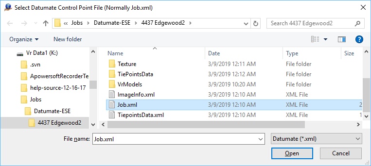
The Select Datumate Control Point File
The Datumate control point file is typically the job file. This is a .xml file and is typically named Job.xml.
Once the two input files are read, the following dialog is displayed indicating the import measurements process is complete.
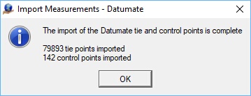
The Import Measurements complete dialog
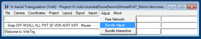
Run the bundle adjustment from the 'Adjust' menu on the main control ribbon. There is no need to open layout, or view images, or anything else.
There will be a prompt for user parameters and after iterating the bundle final tweaking window will open.