Vr Mapping |
ON-LINE REFERENCE DOCUMENTATION CARDINAL SYSTEMS, LLC |
Insert Line (InsLin)
Type: Interactive Application
Places multiple point lines at user-determined locations.
Features and options include:
| • | Splicing the digitized line to an existing line or lines. Click here for more on Splicing |
| • | Support of hydro-enforcement, forcing lines to flow up or downstream, during the collection of line points. |
| • | Point distance control, as determined by the Maximum Segment Length parameter which ensures no two points are further apart than a user defined ground distance. This process is also referred to as densification. |
| • | Support for High/Low point searching in which the lowest, mean or high VrPoint (LiDAR) is found and used according to user defined parameters. Please see High/Low Point Search for more information. |
Local Commands
Key-in |
Description |
Range |
LAY= |
Layer number |
1-32001 |
MOD= |
Mode |
1=Line 2=Spline |
GRP= |
Graphic pointer |
1-1000 |
WID= |
Line width |
0-255 |
PEN= |
Pen number |
1-256 |
CON= |
Construction flag |
0-1 |
NGR= |
Non graphic pointer |
32-bit |
LNK= |
Link number |
32-bit |
FC= |
Feature code |
15 char |
DIG=x y z |
Digitizes point |
X Y Z |
FKEY=name |
Changes to function key parameters |
Function key name |
ARCMOD= |
Arc flag mode |
0 = Don’t place arc flags 1 = Place arc flags |
ENDMOD= |
Sets the behavior of the end button |
0=End 1=Digitize point at current location then end line. 2=Save line after collecting 2 points. 3=Create circle from the 3 points. |
ATTZRU= |
Attaches Z Rule |
0 = Original 1 = Mean 2 = Line 1 (Same as original) 3 = Line 2 (Line attached to) |
ATTNOD= |
Nodes when attaching |
0 = No 1 = Yes |
DRIBAC= |
Drives input device to the previous line point when Backup is pressed |
0 = No 1 = Yes |
RUNONCE= |
If 1 then Insert Line will exit after the next line is saved |
0 = No 1 = Yes |
SPL= |
Turns splicing on/off |
0 = Off 1 = On |
SPLSEA= |
Sets splicing search distance |
Splicing search distance in ground units |
SPLZ= |
Splices Z mode |
0 = Blend elevations from splice line into base line(s) 1 = Inherit the first elevation of the base line for all points on the line after splice 2 = Slope the elevations on the splice line from blend points into the base line(s) |
LAKLIN= |
Makes a Lake Line in which the elevations of the line are set to the first point |
0 = Off 1 = On |
EXPSPL= |
Explodes splined lines. If line mode is splined will place extra points on the line to approximate the spline curve. |
0 = Off 1 = On |
EXPFON= |
Explodes fonted lines. If the line used a non solid line font, multiple lines will be placed to generate the line font graphics. |
0 = Off 1 = On |
EXPSF= |
Explode line scale factor |
If the explode spline option is on, this controls how many points are placed on the line. 1.0 = use normal Spline chord distance. Large numbers add more points, smaller numbers add fewer points. |
MAXSEG= |
Maximum line segment length. Maximum length of any segment on final line. Points will be added to segments longer than this length. All collected points on the line will be kept. See Maximum Segment Length |
Distance in ground units. 0=Do not add points. |
SEGZ= |
Method of interpolating elevations of points added. See Maximum Segment Length |
0=Interpolate from existing points 1=Interpolate from existing DTM surface. 2=Use High/Low point search. |
CLOTWO= |
Allows lines to be closed with only two existing points. |
0=No. Line must have three or more points before it can be closed. 1=Yes. Line can be closed when it has two or more points. |
HYDENF= |
Turns on/off the hydro-enforcement of lines during collection. |
0=Off 1=On |
SCMOD= |
Defines coordinate to be set as Saved Coordinate |
0=First point 1=Last point 2=Lowest point 3=Mean coordinate 4=Highest point |
HYDDIR= |
Defines the flow direction of lines during collection if hydro-enforcement is active. |
0=Downstream 1=Upstream |
Button Assignments
Ins Line - Main
Button |
Description |
1 Digitize pt |
Digitizes a single XYZ location. |
2 Close |
Closes the current line but does not save the line. |
3 Backup |
Deletes the last point on the current line. |
4 End |
Ends and saves the current line. |
5 Attach |
Attaches to an existing line. |
6 Arc |
Fits an arc through the last three line points. |
7 Enter |
Allows entry of line properties or parameters. Also allows the placement of a point by coordinate, azimuth/distance or bearing/distance. |
8 Enter Z |
Allows entry of an elevation. |
9 Attach & run |
Attaches and runs along an existing line copying common points. See Z Rules when using Attach and Run for more information. |
* Menu board |
Makes selection from Menu Board |
0 Toggle snap |
Toggles snapping on / off. |
# End |
Ends Insert Line. |
Ins Line – Enter
Button |
Description |
1 Properties |
Allows entry of line properties such a layer, mode and graphic pointer. |
2 Coordinate |
Allows the placement of a point by entering a coordinate position. |
3 Azimuth |
Allows the placement of a point by azimuth and distance. |
4 Bearing |
Allows the placement of a point by bearing and distance. |
5 |
|
6 |
|
7 Params |
Allows the setting of parameters. |
8 |
|
9 |
|
* |
|
0 |
|
# |
|
Z Rules when using Attach and Run
The following information describes how the Z is handled when using Attach and Run.
If noding is on, then the two node points added to the original line (the one being attached to) are always interpolated from the surrounding original line points.
The Z rule applies to the points added to the new line depending on the current Z rule settings as follows:
| • | Original: The beginning and ending attachment points on the new line are set to whatever the Z value was when digitizing the attachment points. The points added that run along the original line are set to same Z as the original line points. |
| • | Mean: The beginning and ending attachment points on the new line are set to the mean of the active Z and the interpolated Z from the surrounding original line points. The points added that run along the original line are set to same Z as the original line points. |
| • | Line 1: Behaves the same as Original. |
| • | Line 2: The beginning and ending attachment points on the new line are set to the interpolated Z from the surrounding original line points. The points added that run along the original line are set to same Z as the original line points. |
It is possible to splice the current line into another existing line. It is also possible to splice the current line into two existing lines. Parameters may be set to splice automatically based on the position of the end points of the current line. When using Insert Line for splicing, it is not necessary to set any of the line properties such as Layer and Graphic Pointer. The resulting spliced will have the properties from the existing line. If a splice is made between two existing lines, the properties for the new line will be inherited from the first existing line which is the line closest to the start point on the new line.
Splicing is set up by turning on the splicing mode. This can be done from the Enter button (Button 7) then the Params button (Button 7). The splice search distance may be set here also. The splice flag and search distance may also be set from the Spl= and SplSea= key-ins. For example; a key-in of Spl=1 SplSea=20 would turn splicing on and set the search distance to 20 ground units. These key-ins may be placed on a Function Key so Insert Line may be started with splicing set.
One of three splicing elevation modes may be selected when splicing. The splicing Z mode may be set in Parameters (button 7, button 7) in “Splice elevation mode” or may be set with the SplZ= key-in.
| • | Blend (SplZ=0) – The elevations of the end point(s) on the splice line will be blended into the existing line(s). The elevation(s) of the existing line will be used and the elevation(s) of the end points on the splice line will be modified to match. |
| • | Inherit (SplZ=1) – The elevation of the fist point on the existing line will be inherited by all points on the resulting line. After splicing the elevations of all the points on the line will be the same. This is a useful setting when splicing contour lines and should only be used when splicing features such as contours where a constant line elevation is assumed. |
| • | Slope (SplZ=2) – The splice line elevations will be sloped based on the first and last point elevations of the splice line. The first and last points on the splice line will first be blended into the existing line(s) as described in Blend (above), then the remainder of the points on the splice line will be interpolated based on these two elevations. NOTE: Both splice line end points must be blended into an existing line or lines for this option to take effect. If only one end of the splice line is blended, the Blend option will be used for the elevation of that line. |
The results of splicing may be undone using the Undo command.
Following are several examples of splicing:
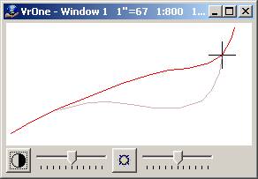
Example 1 – Undershoot Splice
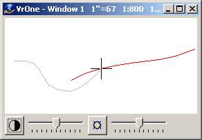
The red line is the existing line and the grey line is the new line. The end point on the new line is within the Splice Search Distance (SplSea=) of the existing line. The first point on the new line is not within the range of an existing line so this end of the line will not be spliced.
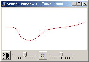
When the new line is ended it is spliced into the existing line. The new line inherits the properties of the existing line.
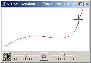
Example 2 – Overshoot Splice
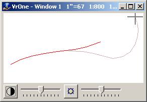
The red line is the existing line and the grey line is the new line. The first point on the new line is within the Splice Search Distance (SplSea=) of the existing line. The last point on the new line is not within the range of an existing line so this end of the line will not be spliced.
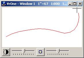
When the new line is ended, it is spliced into the existing line. The new line inherits the properties of the existing line.
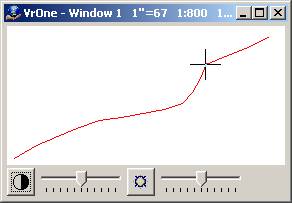
Example 3 – Two Point Splice
The red line is the existing line and the grey line is the new line. Both the first point and end points on the new line are within the Splice Search Distance (SplSea=) of the existing line.
When the new line is ended, it is spliced into the existing line.
Example 4 – Two Line Splice
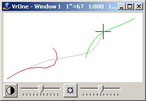
The red and green lines are existing lines and the grey line is the new lines. The first point is within the Splice Search Distance (SplSea=) of the red line and the end point is within the range of the green line.
When the new line is ended, it is spliced into the existing lines. Notice the spliced line assumes the line properties of the first existing line.
It is possible to set a parameter so that no two points are further apart than a user specified distance. The Maximum Segment Length definition will add points to the line for segments longer than this distance. The distance is specified in ground units and a value of zero does not insert any points.
An additional parameter of "Maximum segment length elevation mode" determines how the elevations of the interpolated points are to be computed. Options are as follows:
| • | "Interpolate" : Computes the elevation from the points before and after the added point; |
| • | "Use Z Source": Interpolates the elevation from the active DTM surface if the Z Source is set to "DTM Surface if Active"; |
| • | "Use High/Low search": Uses the current High/Low VrPoint search parameters and applies the results to the interpolated point. |
NOTE: If High/Low searching is turned off or there are no VrPoints in the currently open Workspaces, the "Interpolate" option will be used.
When hydro-enforcement is active, each newly digitized point must conform to the specified elevation flow of the line. If the new point would cause the line to flow in the wrong direction, the alert beep is sounded and the point is ignored. The alert beep sound may be set in Edit Beep (EdiBee). Hydro-enforcement and the flow direction is set in Enter (Button 7) -> Params (Button 7) dialog or may be set using the HydEnf= and HydDir= key-ins.