Vr Mapping |
ON-LINE REFERENCE DOCUMENTATION CARDINAL SYSTEMS, LLC |
Insert Squared Line (InsSqu)
Type: Interactive Application
Inserts a line and squares the line to one of several parameters. Supports squared and un-squared segments and helps with hidden corner placement. Lines may be closed and squared or left open and squared.
Detailed Description
Line segments are rotated about their midpoints to the Square to Azimuth at 0, 90, 180 or 270 degrees and re-intersected with the previous and next segments to square a polygon. Line segments greater than the Squaring Tolerance are not squared. Please note the example below is exaggerated.
Capabilities include:
| • | A hidden corner function, which reads visible tangent line points; |
| • | Support for Attach,which allows the current line to be attached, trimmed, closed, and squared to an existing line. |
| • | Interpolation of a closed, three-point polygon based on the two existing line segments. The resulting squared polygon is a four segment, five-point line. |
See Insert Orthogonal Line (InsOrt) for an interactive application that inserts a squared polygon by observing line segments instead of polygon corners. See Insert Orthogonal Corner (InsOrc) for an interactive application that inserts a squared polygon by reading polygon corners.
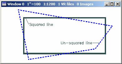
During squaring conformation the following colors are used:
Cyan |
Un-squared line |
White |
Squared line segments |
Red |
Un-squared |
Sequential parallel line segments are removed before squaring.
The squaring tolerance is used to determine parallel lines.
Local Commands
Key-in |
Description |
Range |
LAY= |
Layer number (1-10001L) |
1-10001 |
MOD= |
Mode (1=line 2=spline) |
1=Line 2=Spline |
GRP= |
Graphic pointer (1-60) |
1-60 |
WID= |
Width (0-255) |
0-255 |
PEN= |
Pen number (1-256) |
1-256 |
CON= |
Construction flag (0-1) |
0-1 |
NGR= |
Non graphic pointer (32bit) |
32 bit |
LNK= |
Link number (32bit) |
32 bit |
FC= |
Feature code (15 char) |
48 characters |
FKEY= |
Change to function key properties |
Function key name |
STF= |
Square to flag. |
0-3 0=Longest side 1=Square to azimuth 2=First side 3=Mean of all sides NOTE: This should NOT be used if there are un-squared sides on the polygon. |
AZI= |
Azimuth to square to |
0-360 degrees |
TOL= |
Squaring tolerance |
0-30 degrees |
ATTMOD= |
Allow attaching to existing lines |
0-1 |
ATTDIS= |
Attach search distance |
Ground units |
ATTCOP= |
Close attached line by copying common points |
0-1 |
ATTNOD= |
Node existing line when attaching |
0-1 |
ATTZRU= |
Attach Z Rule |
0-3 |
DRIOPT |
Drive option after squaring |
0=None 1=Drive to first point 2=Drive to last point 3=Drive to centroid |
PARAMETERS
Square to Flag (Stf=)
Specifies the azimuth to which to square the polygon. The available Square to flags are as follows:
0=Longest side
1=Use “Square to azimuth”
2=First side
3=Mean of all sides
NOTE: Flag 3 should NOT be used if there are unsquared sides on the polygon.
Square to Azimuth (Azi=)
The Square to Azimuth is the base azimuth to which all line segments are squared. Each line segment is rotated 0, 90, 180 or 270 degrees from its midpoint to the Square to Azimuth. Line segments outside the Squaring Tolerance are left unsquared.
Squaring Tolerance (Tol=)
Defines the degree measure of a line segment's azimuth greater than which that line segment is left unsquared.
Fkey Name (Fkey=)
Specifies function key from which the new line inherits line parameters. Normally, a function key starts this application and this key-in is not needed.
Attach Mode (AttMod=)
Turns attach mode on/off. If attach in turned on and the first point read on a polygon is within the search distance of an existing line, attach will become active.
Attach Distance (AttDis=)
Defines in ground units the distance that the first point read on a polygon must be within to activate the attach mode.
Attach Copy (AttCop=)
Specifies whether the attached line will be closed by copying common points from the “attach to” line to the new line.
Attach Mode (AttNod=)
Specifies whether the “attach to” line will be noded with one or two points from the end of the new line.
Attach Z Rule (AttZRu=)
Specifies the Z Rule to use when attaching.
Drive Option (DriOpt=)
Specifies the drive action after a line has been squared.
Button Assignments
Ins Square - Main
|
Button |
Description |
1 |
Digitize |
Digitizes a line point. |
2 |
Close |
Closes, squares and saves line. If the current line has three points, the fourth is interpolated based on the two existing line segments. |
3 |
Backup |
Backs up to the previous point. |
4 |
End line |
Squares the line open and saves the line. |
5 |
Hidden corner |
Computes a hidden corner (see below). |
6 |
Dig azimuth |
Digitizes the Square to Azimuth. |
7 |
Enter params |
Enter parameters from dialog box. |
8 |
Toggle squ to |
Cycles through the available Square To options. |
9 |
Toggle squaring |
Turns squaring on/off. |
* |
Menu board |
Make selection from the Menu board. |
0 |
Toggle snap |
Toggles snap on/off. |
# |
End |
Ends Insert Parallel Line. |
Once a line is squared, the verify step determines the action to take on the squared and non-squared line
|
Button |
Description |
1 |
Accept |
Accepts the squaring solution and saves the squared line. |
2 |
Reject |
Rejects the squaring solution discards the collected points. |
3 |
Reject-Continue |
Rejects the squaring solution and returns to the main Insert Squared Line menu. |
4 |
Reject-Save |
Rejects the squaring solution and saves the un-squared line. |
5 |
|
|
6 |
|
|
7 |
|
|
8 |
|
|
9 |
|
|
* |
|
|
0 |
|
|
# |
|
|
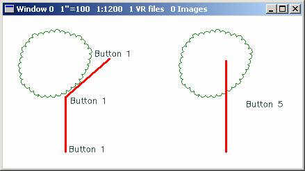
Hidden Corner
The following sequence places a hidden hidden corner. The first button 1 press is read on the building corner. The next two button 1 presses are on the visible roof edge. A final button 5 press computes the hidden corner based on the three previous points.
Attach allows the new line to be attached, trimmed and squared to an existing line. Options include:
| • | Specification of a search distance; |
| • | Ability to close the new line by copying common points from the “Attach to” line; |
| • | Ability to node the “Attach to” line; |
| • | Support for Z Rules. |
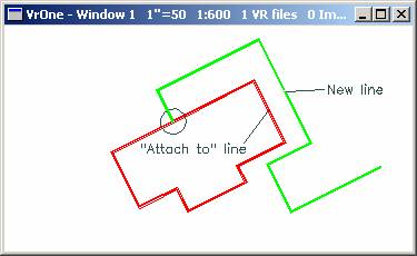
To enable attach, the Attach Mode must be turned on (AttMod=1). If the first point read is within the search distance of an existing line, the attach mode is activated. The line segment of the “Attach to” line closest to the first point will be used to as the “Square to” azimuth for the new line.
NOTE: The last point must be a button 4 (End line) to attach the new line.
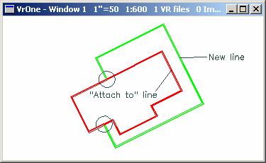
Example 1:
The first and last points are within the search distance of an existing line. The resulting new line is attached, trimmed, and squared to this line. Copy common points is turned off, so the new line is be closed.
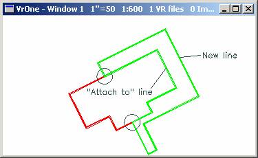
Example 2:
The first point is within the search distance. The resulting new line’s first point is attached and trimmed and the line is squared to the “Attach to” line. The Copy common points parameter is ignored since the last point does not return to the “Attach to” line.
Example 3:
The first and last points are within the search distance of an existing line. The resulting new line is attached, trimmed and squared to this line. Copy common points is turned , so the new line is closed by copying common points from the “Attach to” line.