Vr Mapping |
ON-LINE REFERENCE DOCUMENTATION CARDINAL SYSTEMS, LLC |
Coordinate Projections
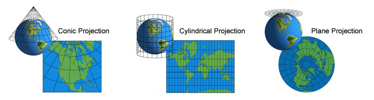
Three basic projections
Setting the Coordinate Projections
Defining a Coordinate Projection
Supported Coordinate Projection Parameters
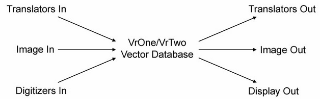
VrOne and VrTwo support coordinate projection transformations during input from translators, images, and digitizers. Coordinate projection transformations are also supported during output to translators, images and the coordinate display in the Main Window and the coordinate display dialog box. In normal usage, it is sufficient to leave coordinate projections turned off and allow VrOne/VrTwo to work in the input coordinate system.
In the above diagram each item may be in a different coordinate projection with transformations performed between each item.
For example, it would be possible to establish the VrOne/VrTwo database coordinate system as state plane in feet but display the current cursor location in one of the coordinate displays as WGS84 in latitude and longitude. Or, for example, it may be necessary to translate State Plane coordinate points from an ASCII file that are in meters into a VrOne file that is using a State Plane coordinate system in feet. By setting the correct projection parameters, the points could automatically be translated from meters to feet during the ASCII In (AscIn) process.
Each coordinate transformation can be turned off or on. If a transformation is turned off then the coordinates will be transferred with no change. If all the coordinate transformations are turned off then the VrOne/VrTwo database coordinate system is undefined and assumes the coordinate system of the inputs. For example, if a model was set using state plane coordinates then the Digitizer In coordinate system would be in state plane also.
For a background and detailed explanation of Map Projections, please visit Carlos A. Furuti's Map Projections site. For a detailed look at map projections, please see the "Map Projections - A Working Manual" from the USGS. For explanations of many grid & datums around the world, please see the "Grid & Datums" column at ASPRS Online.
Setting the Coordinate Projections
The coordinate projections may be set using the Edit Project (EdiPro) command or the Project -> Edit Project pull-down menu.
The input coordinate projections will be transformed to the VrOne/VrTwo coordinate projections. The output coordinate projections will define the transformation from the VrOne/VrTwo coordinate projection to the output coordinate projection.
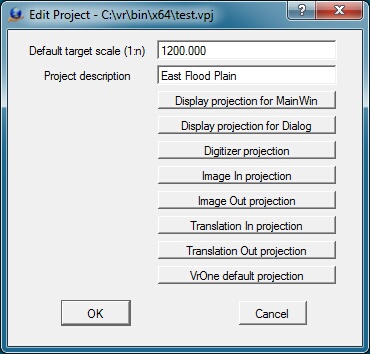
The Edit Project dialog box
Default target scale
Defines the default target scale to assign new VrOne/VrTwo vector files. This value is expressed as a ratio. For example, 1:1200 would be equal to 1"=100'.
Project description
A project description for informational purposes may be entered in this field.
Display projection for MainWin
The right side of the VrOne/VrTwo Main Window displays the current cursor location. This defines the coordinate projection for this coordinate display. If this projection is turned off then coordinates will be displayed in the same coordinate projection as the VrOne/VrTwo file.
Display projection for Dialog
An additional coordinate display may be shown by using the Coordinate Dialog Box (CooDia) command. This defines the coordinate projection for this display. If this projection is turned off, coordinates will be displayed in the same projection as the VrOne/VrTwo file.
Digitizer projection
Defines the coordinate projection for input systems such as the VrTwo model orientation, analog and analytical stereo plotters, Xy digitizers, ADS40, and SOCET SET. If this projection is turned off, the coordinates will be sent without transformation to VrOne/VrTwo in the projection of the input device.
Image in projection
Defines the coordinate projection for images that are used as input. VrOne has the ability to display images such as orthophotos and images such as these are geo-referenced and have a defined coordinate projection. If this projection is turned off the coordinates will be sent to VrOne/VrTwo in the coordinate projection of the image, without transformation.
Image out projection
Defines the coordinate projection for images that are created by Vr Mapping. For example, VrOrtho can set the coordinate projection for the geo-referencing of the output image. If this projection is turned off the coordinates of the image will be in the same coordinate projection of the system that created them. For example, when generating orthophotos, if the coordinate projection is turned off then the coordinate projection will be in the same as the single photo resection coordinate projection.
Translation In projection
The coordinate projection of the input files for such translators such as Dxf and Microstation may be defined with this coordinate projection. If this projection is turned off the coordinates will be sent to VrOne/VrTwo in the projection of the input file, without transformation.
Translation Out projection
The coordinate projection of the output files for such translators such as Dxf and Microstation may be defined with this coordinate projection. If this projection is turned off the coordinates of the output file will be the same coordinate projection as the VrOne/VrTwo file.
VrOne default projection
Each VrOne/VrTwo files coordinate system may be defined in any of the supported coordinate projections. If this projection is turned on then any new VrOne/VrTwo vector files will be set to this coordinate projection. If this coordinate projection is turned off then the VrOne/VrTwo coordinate projection will be undefined. The coordinate projection for a VrOne/VrTwo file may be set at any time after file creation with the Edit Vr Header (EdiVr) command.
Defining a Coordinate Projection
Some or all of the eight possible coordinate projections may be defined.
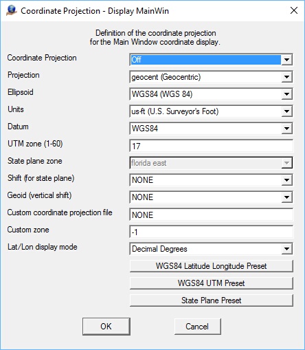
A Coordinate Projection definition dialog box
Coordinate Projection
The status of the coordinate projection can be defined as on or off. If the coordinate projection is turned off then coordinates will be passed with no translation.
Projection
Defines the projection used by this coordinate system. Some common projections are Universal Transverse Mercator (UTM), Polyconic (American). Although it is not a projection, LatLon (Geodesic) is an option and should be chosen when working directly in Geographic coordinates (Latitude and Longitude). It can be useful to set the VrOne database to LatLon when working with ADS40 stereo models to speed up graphics display. Because the ADS40 models are defined using an WGS84 geodetic system, this turns off any time consuming projection computations during ADS40 data collection.
Ellipsoid
The Earth is not exactly spherical, but is closer in shape to an oblate ellipsoid, a shape which bulges around the equator. The Ellipsoid parameter defines the shape of the earth used for the current projection. Common ellipsoids are WGS 84 and GRS 80. WGS84 is used most often and is the ellipsoid used by GPS systems.
Units
Defines the units for this coordinate projection. Choices include us-ft (U.S. Surveyor's Foot), ft (International Foot), and m (Meter).
Datum
Defines the horizontal datum for this coordinate projection. Setting the datum determines how the other projection parameters are used. If the NAD27 or NAD83 datums are chosen, then a State Plane coordinate system is used, and the Sate plane zone number must be specified correctly. Projection and ellipsoid are ignored when State Plane is used. If the UTM datum is chosen, then a UTM zone must be specified correctly.
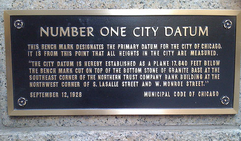
N 41° 52.842 W 087° 37.938 - Marker for the primary datum for the City of Chicago,
the point from which all the heights in the City of Chicago are measured.
UTM zone (1-60)
The Universal Transverse Mercator (UTM) coordinate system is a grid-based method of specifying locations on the surface of the Earth that is a practical application of a 2-dimensional Cartesian coordinate system. It is a horizontal position representation, i.e. it is used to identify locations on the earth independently of vertical position, but differs from the traditional method of latitude and longitude in several respects. The UTM system is not a single map projection. The system instead employs a series of 60 zones, each of which is based on a specifically defined secant transverse Mercator projection.
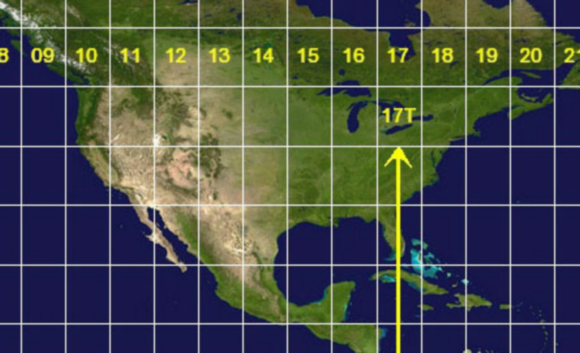
The UTM zones for North America
State plane zone number
The State Plane Coordinate System (SPS or SPCS) is a set of 124 geographic zones or coordinate systems designed for specific regions of the United States. Each state contains one or more state plane zones, the boundaries of which usually follow county lines. There are 110 zones in the continental US, with 10 more in Alaska, 5 in Hawaii, and one for Puerto Rico and US Virgin Islands.
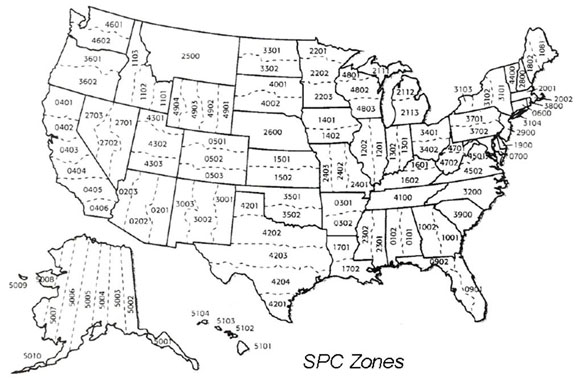
The State Plane Coordinate System
Shift (for state plane)
Defines the North American Datum Conversion (NADCON) grid data file to obtain latitude and longitude shift information for converting between coordinate systems within the United States.
Geoid (vertical shift)
The Earth's shape is neither spherical nor ellipstical; it is a geoidic. The geoid is the equipotential (level) surface that represents best, in a least square sense, the global mean sea level. The Geoid for vertical shift defines the geoid model used by this coordinate system. This is only used when working in the NAD83 State Plane datum. If a Geoid model is specified, elevations will be adjusted real-time to account for the Geoid offsets. If a Geoid model is selected, then the Geoid shift files must be installed to your Vr Mapping installation folder. See Installing the Geoid Files section of the ADS40 tutorial for detailed installation instructions.
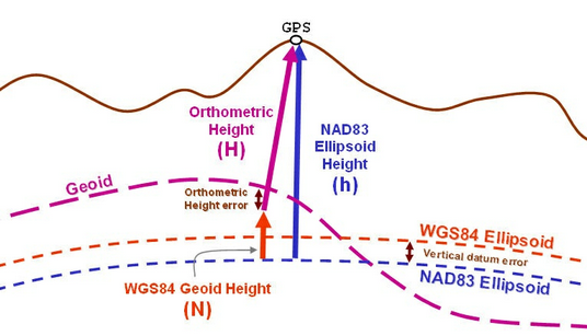
Geoid example
Custom coordinate projection file
A custom projection file may be specified along with a custom zone. The custom projection file should be placed in the \vr\bin\geo folder. It may have any valid filename up to 16 characters. The custom zone is any number up to 5 digits. The settings found in the custom projection file override any settings specified in the projection dialog box.
The custom projection file contains a list of projections defined based on the Proj.4 (http://trac.osgeo.org/proj) parameter syntax. A list of parameters using Proj.4 syntax may be found here (http://trac.osgeo.org/proj/wiki/GenParms) . A good example that shows how custom projections are defined is the nad83 file in the \vr\bin\geo folder. You can use this file as a reference for creating your own custom projections, but be careful not to change anything in the nad83 file.
A sample entry in a custom projection file may look like this:
<500> +proj=utm +ellps=WGS84 +units=m +datum=WGS84 +zone=32 +nc +nocut +nodefs <>
Each entry begins with a number inside left and right arrows (<500>), and usually ends with empty left and right arrows (<>). A single definition may be split across several lines like this:
# 201: arizona east: nad83
<201> proj=tmerc a=6378137 es=.0066943800229
lon_0=-110d10 lat_0=31 k=.9999
x_0=213360 y_0=0
no_defs <>
Any lines beginning with a # symbol are ignored.
To experiment with setting a coordinate projection and rotating a visual map based on the projection, please see http://www.jhlabs.com/java/maps/proj/.
Custom zone
When a custom coordinate projection file or files have been created, this parameter specifies the custom projection to use. In the above example of a custom coordinate projection, a custom zone "201" was created and is referenced for use by setting the "Custom zone" to 201.
Coordinate display decimal places
Defines the number of decimal places, digits to the right of the decimal point, of the coordinates in the VrOne/VrTwo Main Window and the Coordinate Dialog Box (CooDia). This parameter is available for the "Display projection for MainWin" and "Display projection for Dialog".
Lat/Lon display mode
If the coordinate projection of output to the VrOne/VrTwo Main Window or the Coordinate Dialog Box (CooDia) is in latitude/longitude, this parameter defies the display format. Options are "Decimal Degrees", "Degrees, Minutes, Seconds" and "Degrees, Decimal Minutes". This parameter is available for the "Display projection for MainWin" and "Display projection for Dialog".
WGS84 Latitude Longitude Preset
Sets the current parameters to WGS84 latitude longitude. Your projection parameters may be different than this preset.
WGS84 UTM Preset
Sets the current parameters to WGS84 UTM. Your projection parameters may be different than this preset and the setting of the UTM zone is required.
State Plane Preset
Sets the current parameters to State plane. Your projection parameters may be different than this preset and the setting of the State plane zone is required.
Supported Coordinate Projection Parameters
Following are the supported coordinate projection parameters.
Projections
aea (Albers Equal Area)
aeqd (Azimuthal Equidistant)
airy (Airy)
aitoff (Aitoff)
alsk (Mod. Stererographics of Alaska)
apian (Apian Globular I)
august (August Epicycloidal)
bacon (Bacon Globular)
bipc (Bipolar conic of western hemisphere)
boggs (Boggs Eumorphic)
bonne (Bonne (Werner lat_1=90))
cass (Cassini)
cc (Central Cylindrical)
cea (Equal Area Cylindrical)
chamb (Chamberlin Trimetric)
collg (Collignon)
crast (Craster Parabolic (Putnins P4))
denoy (Denoyer Semi-Elliptical)
eck1 (Eckert I)
eck2 (Eckert II)
eck3 (Eckert III)
eck4 (Eckert IV)
eck5 (Eckert V)
eck6 (Eckert VI)
eqc (Equidistant Cylindrical (Plate Caree))
eqdc (Equidistant Conic)
euler (Euler)
fahey (Fahey)
fouc (Foucaut)
fouc_s (Foucaut Sinusoidal)
gall (Gall (Gall Stereographic))
geocent (Geocentric)
geos (Geostationary Satellite View)
gins8 (Ginsburg VIII (TsNIIGAiK))
gn_sinu (General Sinusoidal Series)
gnom (Gnomonic)
goode (Goode Homolosine)
gs48 (Mod. Stererographics of 48 U.S.)
gs50 (Mod. Stererographics of 50 U.S.)
hammer (Hammer & Eckert-Greifendorff)
hatano (Hatano Asymmetrical Equal Area)
imw_p (International Map of the World Polyconic)
kav5 (Kavraisky V)
kav7 (Kavraisky VII)
krovak (Krovak)
labrd (Laborde)
laea (Lambert Azimuthal Equal Area)
lagrng (Lagrange)
larr (Larrivee)
lask (Laskowski)
lonlat (Lat/long (Geodetic))
latlon (Lat/long (Geodetic alias))
latlong (Lat/long (Geodetic alias))
longlat (Lat/long (Geodetic alias))
lcc (Lambert Conformal Conic)
lcca (Lambert Conformal Conic Alternative)
leac (Lambert Equal Area Conic)
lee_os (Lee Oblated Stereographic)
loxim (Loximuthal)
lsat (Space oblique for LANDSAT)
mbt_s (McBryde-Thomas Flat-Polar Sine (No. 1))
mbt_fps (McBryde-Thomas Flat-Pole Sine (No. 2))
mbtfpp (McBride-Thomas Flat-Polar Parabolic)
mbtfpq (McBryde-Thomas Flat-Polar Quartic)
mbtfps (McBryde-Thomas Flat-Polar Sinusoidal)
merc (Mercator)
mil_os (Miller Oblated Stereographic)
mill (Miller Cylindrical)
moll (Mollweide)
murd1 (Murdoch I)
murd2 (Murdoch II)
murd3 (Murdoch III)
nell (Nell)
nell_h (Nell-Hammer)
nicol (Nicolosi Globular)
nsper (Near-sided perspective)
nzmg (New Zealand Map Grid)
ob_tran (General Oblique Transformation)
ocea (Oblique Cylindrical Equal Area)
oea (Oblated Equal Area)
omerc (Oblique Mercator)
ortel (Ortelius Oval)
ortho (Orthographic)
pconic (Perspective Conic)
poly (Polyconic (American))
putp1 (Putnins P1)
putp2 (Putnins P2)
putp3 (Putnins P3)
putp3p (Putnins P3')
putp4p (Putnins P4')
putp5 (Putnins P5)
putp5p (Putnins P5')
putp6 (Putnins P6)
putp6p (Putnins P6')
qua_aut (Quartic Authalic)
robin (Robinson)
rouss (Roussilhe Stereographic)
rpoly (Rectangular Polyconic)
sinu (Sinusoidal (Sanson-Flamsteed))
somerc (Swiss. Obl. Mercator)
stere (Stereographic)
sterea (Oblique Stereographic Alternative)
tcc (Transverse Central Cylindrical)
tcea (Transverse Cylindrical Equal Area)
tissot (Tissot)
tmerc (Transverse Mercator)
tpeqd (Two Point Equidistant)
tpers (Tilted perspective)
ups (Universal Polar Stereographic)
urm5 (Urmaev V)
urmfps (Urmaev Flat-Polar Sinusoidal)
utm (Universal Transverse Mercator (UTM))
vandg (van der Grinten (I))
vandg2 (van der Grinten II)
vandg3 (van der Grinten III)
vandg4 (van der Grinten IV)
vitk1 (Vitkovsky I)
wag1 (Wagner I (Kavraisky VI))
wag2 (Wagner II)
wag3 (Wagner III)
wag4 (Wagner IV)
wag5 (Wagner V)
wag6 (Wagner VI)
wag7 (Wagner VII)
weren (Werenskiold I)
wink1 (Winkel I)
wink2 (Winkel II)
wintri (Winkel Tripel)
Ellipsoids
MERIT (MERIT 1983)
SGS85 (Soviet Geodetic System 85)
GRS80 (GRS 1980(IUGG, 1980))
IAU76 (IAU 1976)
airy (Airy 1830)
APL4.9 (Appl. Physics. 1965)
NWL9D (Naval Weapons Lab., 1965)
mod_airy (Modified Airy)
andrae (Andrae 1876 (Den., Iclnd.))
aust_SA (Australian Natl & S. Amer. 1969)
GRS67 (GRS 67(IUGG 1967))
bessel (Bessel 1841)
bess_nam (Bessel 1841 (Namibia))
clrk66 (Clarke 1866)
clrk80 (Clarke 1880 mod.)
CPM (Comm. des Poids et Mesures 1799)
delmbr (Delambre 1810 (Belgium))
engelis (Engelis 1985)
evrst30 (Everest 1830)
evrst48 (Everest 1948)
evrst56 (Everest 1956)
evrst69 (Everest 1969)
evrstSS (Everest (Sabah & Sarawak))
fschr60 (Fischer (Mercury Datum) 1960)
fschr60m (Modified Fischer 1960)
fschr68 (Fischer 1968)
helmert (Helmert 1906)
hough (Hough)
intl (International 1909 (Hayford))
krass (Krassovsky, 1942)
kaula (Kaula 1961)
lerch (Lerch 1979)
mprts (Maupertius 1738)
new_intl (New International 1967)
plessis (Plessis 1817 (France))
SEasia (Southeast Asia)
walbeck (Walbeck)
WGS60 (WGS 60)
WGS66 (WGS 66)
WGS72 (WGS 72)
WGS84 (WGS 84)
sphere (Normal Sphere (r=6370997))
Units
km (Kilometer)
m (Meter)
dm (Decimeter)
cm (Centimeter)
mm (Millimeter)
kmi (International Nautical Mile)
in (International Inch)
ft (International Foot)
yd (International Yard)
mi (International Statute Mile)
fath (International Fathom)
ch (International Chain)
link (International Link)
us-in (U.S. Surveyor's Inch)
us-ft (U.S. Surveyor's Foot)
us-yd (U.S. Surveyor's Yard)
us-ch (U.S. Surveyor's Chain)
us-mi (U.S. Surveyor's Statute Mile)
ind-yd (Indian Yard)
ind-ft (Indian Foot)
ind-ch (Indian Chain)
Datums
WGS84
GGRS87 (Greek_Geodetic_Reference_System_1987)
NAD83 (North_American_Datum_1983)
NAD27 (North_American_Datum_1927)
potsdam (Potsdam Rauenberg 1950 DHDN)
carthage (Carthage 1934 Tunisia)
hermannskogel (Hermannskogel)
ire65 (Ireland 1965)
nzgd49 (New Zealand Geodetic Datum 1949)
OSGB36 (Airy 1830)
Shift for State Plane
NONE
alaska
alhpgn
arhpgn
azhpgn
cnhpgn
cohpgn
conus
cshpgn
emhpgn
eshpgn
ethpgn
flhpgn
gahpgn
guhpgn
hawaii
hihpgn
iahpgn
ilhpgn
inhpgn
kshpgn
kyhpgn
lahpgn
MD
mdhpgn
mehpgn
mihpgn
mnhpgn
mohpgn
mshpgn
nbhpgn
ndhpgn
nehpgn
njhpgn
nmhpgn
nvhpgn
nyhpgn
ohhpgn
okhpgn
pahpgn
prvi
pvhpgn
sdhpgn
stgeorge
stlrnc
stpaul
TN
tnhpgn
uthpgn
vahpgn
WI
wihpgn
wmhpgn
WO
wohpgn
wshpgn
wthpgn
wvhpgn
wyhpgn
Geoids (vertical shift)
NONE
GEOID12A
GEOID12B
GEOID03
GEOID06
GEOID09
GEOID96
GEOID99
USGG2003
USGG2009
USGG2012
G99SSS
Note: GEOID99 supersedes GEOID96 which has not been tested (6/29/16)
The geoid data files may be downloaded from the Vr Mapping software download page. The geoid data files are from the National Geodetic Survey (NGS) and more information on geoids can be found at http://www.ngs.noaa.gov/GEOID/
Warning
The process of coordinate projection transformation changes coordinate values and involve many parameters that influence the output. It is important that the user understand coordinate projections and their associated parameters. It is also important that the results of any transformation be thoroughly checked before use. The coordinate projection computations that are described above are based on the PROJ.4 Cartographic Projection Library. Please see the PROJ.4 website at http://trac.osgeo.org/proj/ for more information including license information and disclaimers.
CARDINAL SYSTEMS, LLC DISCLAIM ALL WARRANTIES WITH REGARD TO THIS SOFTWARE, INCLUDING ALL IMPLIED WARRANTIES OF MERCHANTABILITY AND FITNESS, IN NO EVENT SHALL CARDINAL SYSTEMS, LLC BE LIABLE FOR ANY SPECIAL, INDIRECT OR CONSEQUENTIAL DAMAGES OR ANY DAMAGES WHATSOEVER RESULTING FROM LOSS OF USE, DATA OR PROFITS, WHETHER IN AN ACTION OF CONTRACT, NEGLIGENCE OR OTHER TORTIOUS ACTION, ARISING OUT OF OR IN CONNECTION WITH THE USE OR PERFORMANCE OF THIS SOFTWARE.
If you disagree with the above warning and disclaimer, please do not use coordinate projections in VrOne/VrTwo. These coordinate projections may be turned off as described above.