Vr Mapping |
ON-LINE REFERENCE DOCUMENTATION CARDINAL SYSTEMS, LLC |
VrTwo Orientation - Single Model Import of ISAT Exterior Orientations
VrTwo Orientation Tutorial Manual Import Exterior Orientation Method
VrTwo Orientation creates stereo image pairs (or models) for viewing in VrTwo and VrLite. Stereo models may be generated manually or by importing the results from various aerial triangulation programs. Orientations may be performed on a single model or multiple models in a batch mode. Models may be imported from aerial triangulation using exterior orientations or the measurements used to tie images and strips together. This tutorial will address importing orientations for a single model using the ISAT exterior orientation file.
Creating or Editing the Camera File
New Camera (NewCam)
Allows the user to create and edit a new camera calibration file. Prompts user for the new camera's file name. Camera files in Vr Mapping have the .cam file name extension. See Edit Camera below for information on editing a camera file. If a preexisting camera file exists, this feature may not be needed.
Creating the Camera File
From the "Camera" dropdown menu, click on either "New Camera" or "Edit Camera".
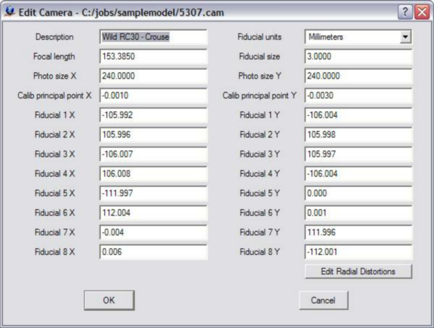
The Edit Camera dialog box
Creating or Editing a Control File
If one does not already exist, create a new coordinate file. From the "Coordinates" dropdown menu, click on "New Coordinate File". Please see VrTwo Orientation New Coordinate File for more information.
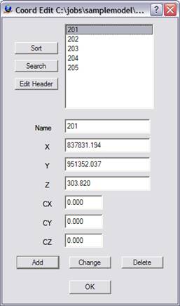
The Edit Control dialog box
If a control file exists and contains the PointName X Y Z fields, it can be used directly by Vr Mapping programs. Simply rename the file by replacing the file postfix with .cor. For example, if there were a coordinate file named TheCoords.txt which contained the PointName XYZ fields, it could be renamed TheCoords.cor and be used by VrTwo Orientation.
The following is an example of a contents of a coordinate file compatible with Vr Mapping:
201 837831.194130 951352.037020 303.8200
202 836399.079330 951266.642540 337.6800
203 837994.618340 950634.951710 299.6000
204 836711.670600 950565.198920 326.3200
205 836018.411470 950724.804370 309.2900
The first field is the point name followed by the X, Y and Z coordinates.
Creating or Editing the Project
The following steps create the project:
| 1. | Create a New Project File - From the "Project" dropdown window, click on either "New Project" or "Edit Project". |
| 2. | Add Coordinate File - Click the button to the right of the “Coordinates” box to add the coordinate file name. |
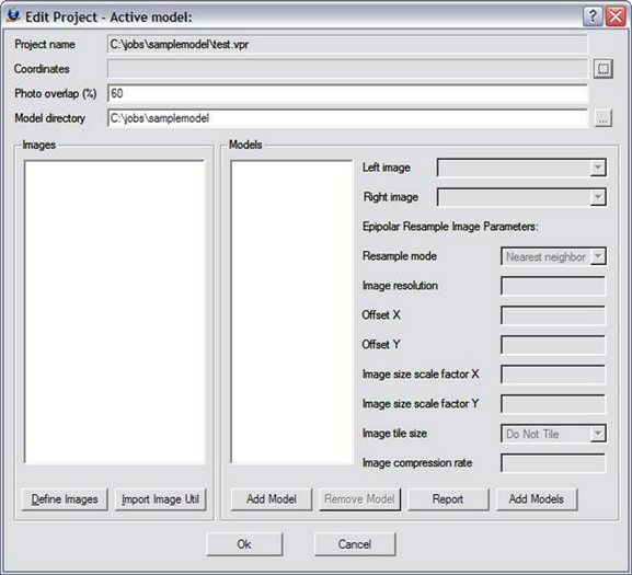
The Edit Project dialog box prior with no parameters defined
3. Define Images - Click the "Define Images" button in the "Edit Project" dialog box. The "Edit Project - Define Images" dialog box allows the definition of multiple image files. Each image file has a Photo Name Format, which are parameters that define the strip and photo number from an image file name. Strip direction, pixel size and the "Open in Layout" flag may also be defined for each image. The top portion of the dialog box is a template of these parameters. This template may be copied to an image or a group of images by selecting the desired file(s) then pressing the "Apply" button.
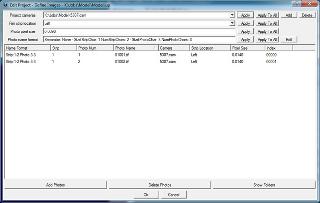
The Edit Project - Define Images dialog box
The following are descriptions of the parameters in the "Edit Project - Define Images" dialog box:
Project Camera
Project cameras (.cam) are assigned to individual images. Up to 10 camera files may be defined.
Film Strip Location
Defines the direction flight. For more information please see VrTwo Orientation - Film Strip Direction.
Photo Pixel Size
The photo pixel size is in the same fiducial units (millimeters, inches, or pixels) defined by the Camera file. If this value is unknown, it can be computed after reading three points in Inner Orientation at the bottom left of the Interior Orientation window.
Add Photos
Adds images to the project.
Photo Name Format
Sets the parameters that define the strip and photo number from an image file name. For more Information please see VrTwo Orientation - Photo Name Format.
4. Create Model Names
Click "Add Model" to create a new model. Pressing this button allows a single model to be added to the list of models. After the model is added, the left and right images must be selected and the epipolar re-sampling image parameters must be set.
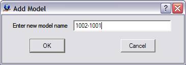
The Add Model dialog box
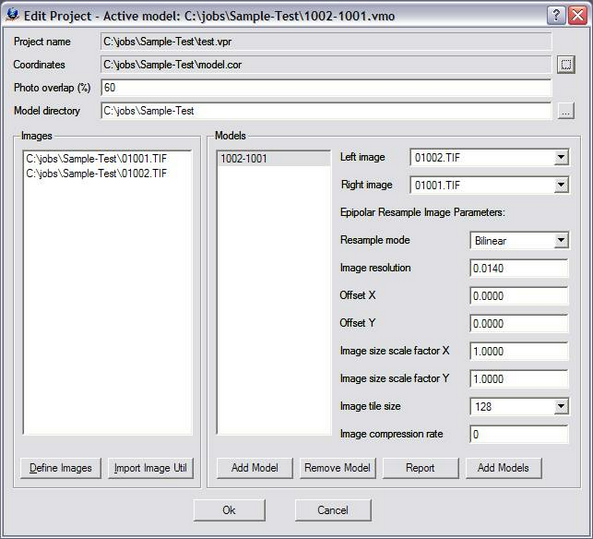
The Edit Project dialog box showing Model 1002-1001
Please see VrTwo Orientation - Project for more information.
Section 2 Importing Orientations
Importing Interior Orientations in Batch Mode
Although this tutorial describes the import of a single model from Exterior Orientations, it is possible to import Interior Orientations in a batch mode.
| 1. | Select "Import Interior Orientations Batch" from the "Import" dropdown menu. |
| 2. | Select the ISAT Photo File name and Interior Orientation file format. |
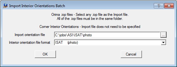
The Import Interior Orientations Batch dialog box
Import Orientation File - Defines the name of the ISAT parameter file that contains orientation parameters. This file is normally named "photo".
Interior Orientation File Format - Defines the input format. Should be "ISAT (photo)".
| 3. | Select the strip number location, which defines the location of the strip number in the "photo" file. Review the ISAT photo file to see if the strip number is encoded with the photo name after the "photo_measurements" keyword or follows the "strip_id" keyword. In the example below the strip number is part of the photo name . For more information, see ISAT Photo File Format. |
begin photo_measurements 01-02 strip_id 01 version 2.0
21370307 -12.313744 -61.250663 -12.312909 -61.246508 1 85
21370297 -3.3020941 -68.078501 -3.3018724 -68.073928 1 85
21370317 -5.2376813 -75.449179 -5.2373545 -75.44447 1 85
21370322 -14.481854 -68.898072 -14.480887 -68.89347 1 85
21370344 -0.68857854 -82.631939 -0.68853523 -82.626727 1 85
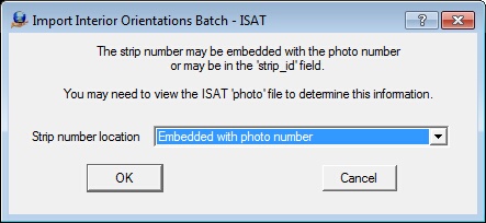
Defining the location of the strip number in the "photo" file
| 5. | Set Strip Photo Separator - Defines the file format of the image names and determines how the strip and photo number are parsed by VrTwo Orientation. The Photo Name Format dialog is displayed if the Strip Number Location is set to "Embedded with photo number" in the previous prompt. For more information see Photo Name Format. |
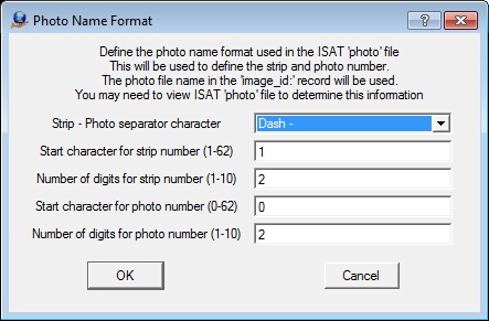
The Photo Name Format dialog box
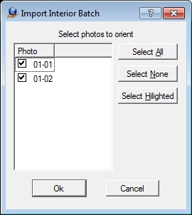
| 6. | Select Photos To Import - Sets the photos to be used in the model. |
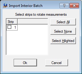
| 7. | Select Strip Reversal - If a strip is checked, its measurements are rotated 180 degrees. This may be necessary for strips with Strip Location to the right. |
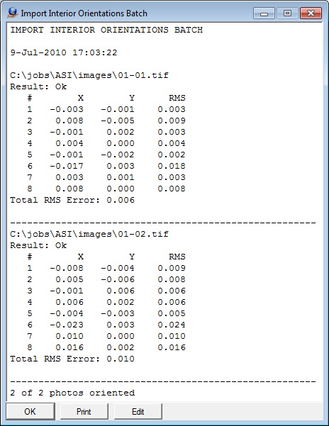
| 8. | Start the Import by clicking "OK". Results and residuals will be presented as shown below. |
| 9. |
Importing Exterior Orientations
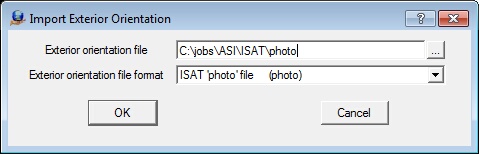
| 1. | Select "Import" from the "Exterior Orientation Single" dropdown menu. |
| 2. | Set "Exterior orientation file format" to "ISAT 'photo' file". |
| 3. | Select the Exterior Orientation file or Photo file. |
4. Select Strip Number Location - Specifies whether the strip number is embedded with the photo name. Review the ISAT photo file to see if the strip number is embedded
with the photo number. In the example below, the strip number is part of the photo name. For more information, please see ISAT photo file format.
begin photo_measurements 01-02 strip_id 01 version 2.0
21370307 -12.313744 -61.250663 -12.312909 -61.246508 1 85
21370297 -3.3020941 -68.078501 -3.3018724 -68.073928 1 85
21370317 -5.2376813 -75.449179 -5.2373545 -75.44447 1 85
21370322 -14.481854 -68.898072 -14.480887 -68.89347 1 85
21370344 -0.68857854 -82.631939 -0.68853523 -82.626727 1 85
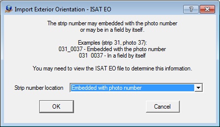
The Import exterior Orientation dialog box that defines the location of the strip number in the ISAT 'photo' file
| 5. | Set Strip Photo Separator - Defines the file format of the image names and determines how strip and photo number are parsed by VrTwo Orientation. |
For more information, please see Photo Name Format.
The Photo Name Format definition dialog box
6. The two images to use for orientation are selected by choosing the "Left photo" and "Right photo. The exterior orientation file and number of images read is shown along with the current model at the top of the dialog box.
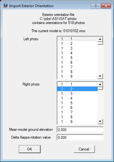
The Import Exterior Orientation photos selection dialog box
Following are the definitions for the two fields below the image selection area in the Import Exterior Orientation dialog box.
Mean Model Ground Elevation
Defines the average ground elevation of the model or job. This may be approximate.
Delta Kappa Rotation Value
Some situations require a rotation angle to be added to the Kappa (rotation about the Z axis) value in the exterior orientation file. This will be required if the images were rotated from their original positions. It is suggested that an angle of zero is first attempted. If the import does not produce a viewable stereo model, a rotation value of 180 should be entered. The possible rotation values are 0, 90, 180, and 270 degrees.
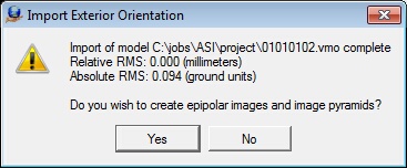
| 7. | Review the Orientation Results provided in the dialog box and click "Yes" to create epipolar images and epipolar image image pyramids. |
The Main Window will display the progress of the epipolar image creation.
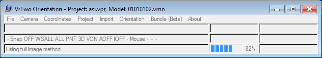
VrTwo Orientation creating Epipolar images.
Section 3 Opening Model in VrTwo
1. Start VrTwo.
2. Click on File -> Open Model or use the Open Model (OpeMod) command. Navigate to the location of the project folder by double clicking the far left hand box.
3. Double click the VrTwo Model (.vmo) file then press "OK".
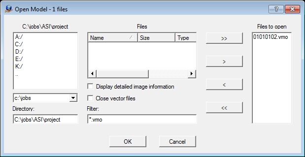
The Open Model dialog box
4. VrTwo will now generate pyramids for the epipolar images if they do not already exist.
5. Open a VrOne File by clicking on File -> Open Vr File or by using the Open VrOne File (OpeVr) command. Navigate to the project folder by double clicking in the far left hand box.
6. Double click the VrOne (.vr) file and press "OK".
The stereo model should open. The stereo model and vectors should be seen on the screen. If the stereo window does not show a stereo image and vectors, try using the Drive Control (Cd) command. Typing "Cd 1" will drive to the first control point in the model. For more information, please see the Getting started with VrOne/VrTwo tutorial, which covers basics of data collection and editing.
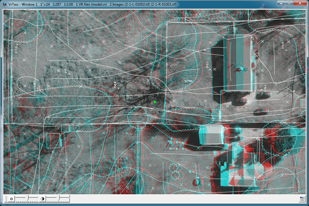
The VrTwo graphics window showing the stereo model (Anaglyph)