Vr Mapping |
ON-LINE REFERENCE DOCUMENTATION CARDINAL SYSTEMS, LLC |
VrTwo Orientation
Type: Stand-alone application (vr2ori.exe)
Photogrammetric stereo model orientation program for Vr Mapping's VrTwo softcopy environment
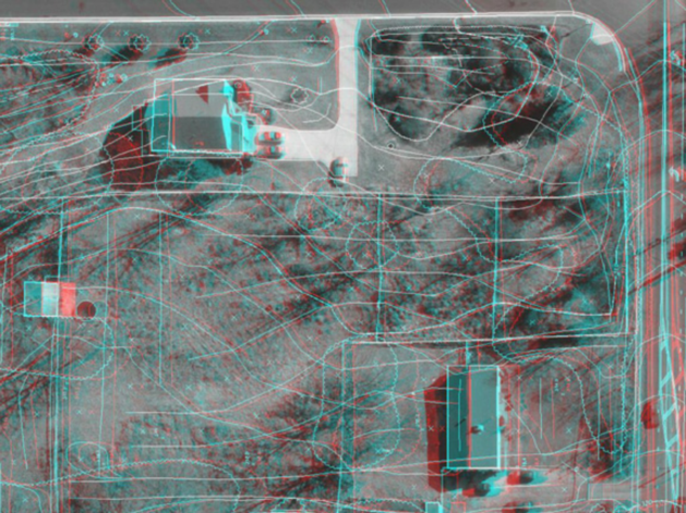
A stereo model (Anaglyph)
Interior Orientations – Batch (IntBat)
Exterior Orientation – Single (ImpExt)
Exterior Orientations – Batch (ExtBat)
Measurement Orientation – Single
Measurement Orientations – Batch (MeaBat)
Measurement Orientation Parameters (MeaPar)
Create Epipolar Images – Batch (CreEpi)
Left Interior Orientation (LefInt)
Right Interior Orientation (RigInt)
Corner Interior Orientations (CorInt)
View Relative Orientation 3D (VieRel)
Relative Orientation Parameters (RelPar)
Left and Right Image Rotations
Vr Mapping Coordinate File Format
Overview
VrTwo Orientation creates stereo image pairs or models to be viewed in VrTwo and VrLite. Stereo models may be generated manually or by importing the results from various aerial triangulation programs. Orientations may be performed on a single model, or multiple models may be oriented in a batch mode. Models may be imported from aerial triangulation by their exterior orientations or from the measurements used to tie the images and strips together.
VrTwo Orientation will start by opening the Main Window.
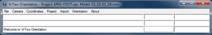
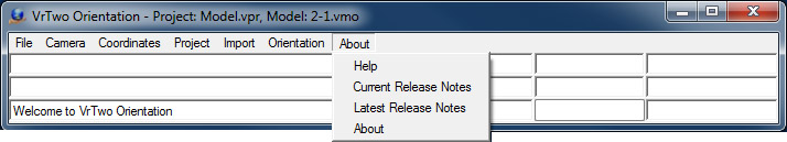
The VrTwo Orientation Main Window
Starting an Application (Command)
Start commands by selecting an item from a dropdown menu. Alternatively, start commands with a key-in using the command name.
The Main Window in VrTwo Orientation contains the command pull down menus, a key-in area, two information areas, a progress bar, and the coordinate display. Command names may be entered in the key-in area. The active project name is displayed in the border of the Main Window.
VrTwo Orientation’s main purpose is to create stereo models containing left and right image pairs that can be used by VrTwo. These models consist of left and right epipolar images and an orientation parameter file. The parameter file has the extension .orp and contains the orientation parameters required for VrTwo to work with stereo images. VrTwo Orientation is project based and requires a project to be created before any processing can be done. A project in VrTwo Orientation comprises a list of images, camera files, and model definitions. Each project in VrTwo Orientation is divided into models. Each model contains one left image and one right image, resulting in a stereo image pair.
The following files are needed to set a stereo model.
| • | Images with overlap suitable for stereo viewing. This overlap is normally 60%. |
| • | A camera calibration. This will be used to create a Vr Mapping camera (.cam) file |
| • | A ground coordinate file. |
| • | An exterior orientation or measurement file from aerial triangulation if importing orientations. |
The following is a typical workflow for VrTwo orientations.
1. Create the camera calibration (.cam) file.
2. Create the VrTwo orientation project.
3. Create or import interior orientations.
4. Perform relative and absolute orientations manually, or import them from aerial triangulation exterior orientations or image measurements.
The Vr Image Utility program may be used to prepare the images for the project by attaching the strip location, image pixel size, and camera to each image. It can also be used to perform automatic interior orientations. The VrTwo orientation program also can set up the images for the project. If several programs (such as VrTwo Orientation, Vr Orthophoto, and Vr Aerial Triangulation) will use the same images, Vr Image Utility should be used to set up the images so the other programs may import the project file.
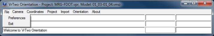
The File Menu
Sets operating parameters for the VrTwo Orientation Program.
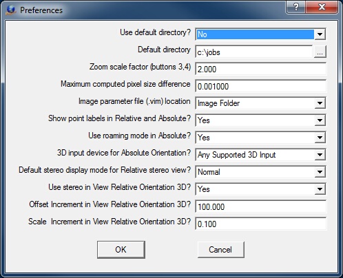
The VrTwo Orientation Preference dialog box
Use default directory?
Specifies whether to use the default directory. The default directory is used as the start directory for items like dialog boxes where files may be selected.
Default directory
Defines the default directory to use provided that “Use default directory” is set to "Yes".
Zoom scale factor (buttons 3,4)
Sets the scale factor to use when zooming in and out with the mouse center button.
Maximum computed pixel size difference
Defines the maximum difference that computed pixel sizes can be from entered pixel size before a warning will be displayed when exiting inner orientation. 0.0 = Don't check pixel size difference.
Image parameter file (.vim) location
Each image used in the VrTwo orientation program has an associated parameter (.vim) file. This file contains the interior orientation values and other image parameters. The image parameter file has the same name as the image but with a .vim file extension. These parameter files may be stored in the same directory (folder) as the images or they may be stored in the project folder. The two options for this value are Image Folder and Project Folder.
Show point labels in Relative and Absolute?
When making observations in relative and absolute orientations point labels that show the point sequence number follow the measuring mark. These labels may be turned off if needed. Some graphics cards a slow when updating these labels and turning off the labels is necessary.
Use roaming mode in Absolute?
If set to "Yes", then roaming stereo graphics will be used in Absolute Orientation. If set to "No", then static stereo graphics will be used for Absolute Orientation.
3D input device for Absolute Orientation?
Sets what type of 3D input device to use for Absolute Orientation. Choices are "Mouse Only" or "Any Supported Input 3D Input". If set to "Any Supported Input 3D Input", the the current "XYZ Digitizer" configured for VrTwo will be used.
Default stereo display mode for Relative stereo view?
Sets stereo mode to "Anaglyph" or "Normal" by default when using the Relative orientation stereo view.
Use stereo in View Relative Orientation 3D
When using the view relative orientation 3D function from the Orientation pull-down it is possible to view the model configuration in true 3D. This is possible if the computer has the necessary 3D hardware.
Offset Increment in View Relative Orientation 3D
The view relative orientation 3D function allows the interactive placement of the model view point offsets. This parameter is used as the increment when adjusting the offsets.
Scale Increment in View Relative Orientation 3D
The view relative orientation 3D function allows the interactive modification of the image size scale factors. This parameter is used as the increment when adjusting these scale factors.
Exits VrTwo Orientation.
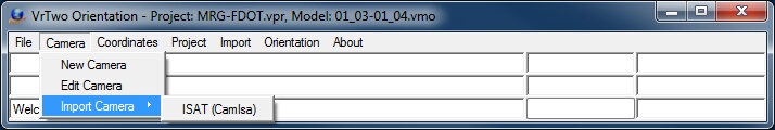
The Camera menu
The camera menu is used to create, edit and import camera calibration parameters.
The New Camera allows the user to create and edit a new camera calibration file. The user will be prompted for the file name for the new camera. Camera files in Vr Mapping have the .cam file name extension. See Edit Camera below for information on editing a camera file.
Edit Camera allows the user to edit an existing camera calibration file. The camera edited does not need to be one of the current cameras and any existing camera file may be edited. When edit camera is started the user will be prompted for a camera file name and when exiting the user will have the opportunity to save the modified camera calibration parameters.
NOTE: The camera calibration values for the photo size and Calibrated Principal Point should be entered from the calibration report using a strip location of left or zero rotation. One camera calibration (.cam) file is used for all image rotations during model orientation. Please refer to the project camera calibration report to determine the zero rotation (strip location left) orientation of the images for your project. Please see Left and Right Image Rotations for more information on model image rotations.
NOTE: If Corner Interior Orientations are used then the photo size is automatically set by using the photo pixel size defined in Project -> Edit Project -> Define Images.
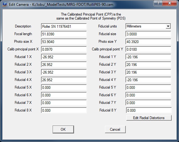
Description
Describes the camera for user reference. This description is for information only and is not used in model orientation.
Fiducial units
Specifies the units of the coordinate positions (millimeters, inches, or pixels). Many programs used to calibrate handheld cameras output the focal length of the camera in pixels. The coordinates entered to represent the fiducial positions must be in the same units as those specified here.
Focal length
Defines the camera lens' focal length, the distance from the focal point to the center of the lens. This value is provided by the camera calibration report. Focal length units should be the same as those used for the fiducial positions.
Photo size X Y
Specifies image dimensions. Photo size dimensions should be the same as those used for the fiducial positions.
Calib principal point X Y
Specifies the calibrated principal point (also known as the point of best symmetry). This coordinate position is available from the camera calibration report. Calibrated principal point coordinate units should be the same as those used for the fiducial positions.
Fiducial X Y
Defines coordinate positions for up to eight fiducials in the user-specified Fiducial units. Most aerial cameras have eight fiducials. It is strongly recommended that all eight be entered and used to compute interior orientation. If only four fiducials are used, errors may occur and make residuals useless in determining if the wrong camera calibration was selected.
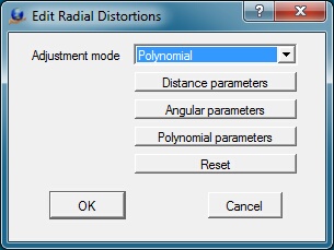
Lens distortion causes image positions to be displaced from their ideal or true locations. In aerial cameras, these distortions are normally minimal but they can still have an effect on accuracy. Some digital cameras have large lens distortions and radial distortions must be entered for accurate mapping results.
Adjustment mode
Most camera calibration programs output radial distortion values as polynomial parameters. Though angular parameters are listed, this output type is currently unsupported.
Distance Parameters
Radial distortions, represented by concentric rings about the camera lens' calibrated principal point, may be entered as distance parameters. The radial distortions shown below are from a small format camera and show high radial distortion values.
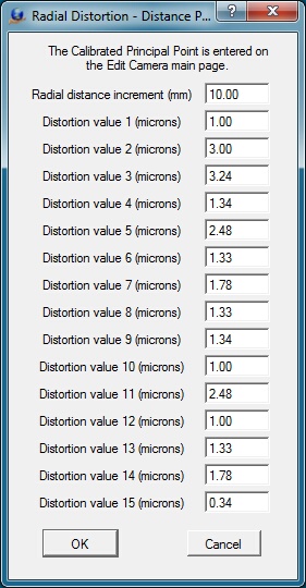
Defining radial distortions by distance
Radial distance increment
Represents the distance between the concentric rings that make up the distance parameters. Radial distance increment units should be the same as those used for Fiducial positions.
Distortion value n
Specifies distortion values for each distance. There may be up to 15 values. Distortion value units should be the same as those used for Fiducial positions.
Angular Parameters
Computation of radial distortions by angular parameters is currently unsupported. Please use distance or polynomial parameters.
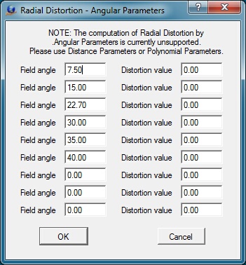
Defining radial distortions by angle
Polynomial Parameters
The polynomial values and principal point or autocollimation are provided by the camera calibration report. The mathematical model used is based on the Simultaneous Multi-camera Analytical Calibration (SMAC) method. Care should be taken when entering these parameters, as entry errors cause model orientation errors and distortions which affect model accuracy.
Entry of Exponential Notation
The k0-k4 values and the p1-p4 values are entered into the Polynomial Parameters dialog box in exponential notation. The values entered from the USGS camera calibration report may have the decimal place moved one position to the left depending on the number entered. For example:
USGS value: 0.1403x10⁻³
Value typed: .1043e-3
Shown value: 1.403000e-004
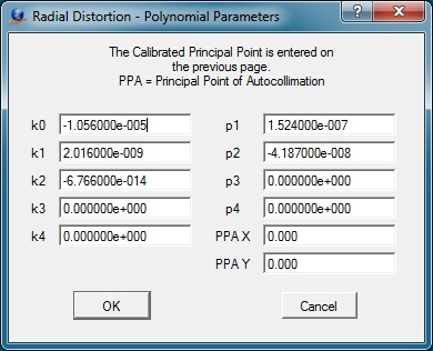
The Radial Distortions dialog box for entering the polynomial parameters
K0-K4
Defines up to five K coefficient values. These are coefficients of symmetric radial lens distortion from the camera calibration report. These values are entered in exponent form.
P1-P4
Defines to four P coefficient values. These are the coefficients of de-centering distortion from the camera calibration report. These values are entered in exponent form.
ISAT (CamIsa)
Imports camera calibrations from an ISAT file. The ISAT file can contain several camera definitions.
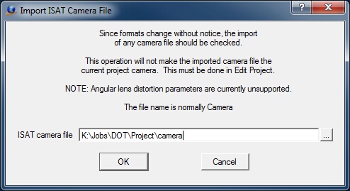
Import ISAT camera file dialog box
ISAT camera file
Defines the ISAT camera file. Normally named "camera".
Coordinates
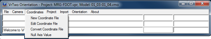
The Coordinates menu provides functions to create and edit coordinate files. It is possible to import existing coordinate files with a simple name change. Please refer to Vr Mapping Coordinate File Format for information on the format and layout of the coordinate files used in VrTwo.
Creates a new coordinate file. The Format, State Plane Zone, Datum, UTM Zone and Units in the Edit Header dialog box are for user reference only. Prompts the user for a coordinate file name and coordinate file parameters.
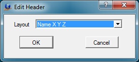
The New Coordinate dialog box
Layout
Specifies the fields to be placed in the coordinate file and their order. Options are:
Name X Y Z Cx Cy, Cz
Name Y X Z Cy Cx, Cz
X Y Z Name Cx Cy, Cz
Y X Z Name Cy Cx, Cz
Name X Y Z
Name Y X Z
X Y Z Name
Y X Z Name
X Y Name
Y X Name
Where:
Name – Point name
X Y Z – Coordinates
Cx Cy Cz – X Y Z point weights
Edits coordinates in an existing coordinate file. Editing options include Add, Change, and Delete. When this command is started, the user can open any coordinate (.cor) file and the edited file may be saved upon exiting the application.
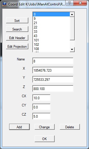
The Edit Coordinates dialog box
Sort
Sorts the coordinate file based on the point name.
Search
Searches for a coordinate point by name. If the point name is found, it becomes the current point.
Edit Header
Edits the coordinate file header.
Name
Defines the point name. It must be alphanumeric and may be up to 32 characters in length.
X Y Z
Defines coordinate values for the point.
CX CY CZ
Defines point weights. These may be used in the coordinate file depending on the File Layout. Normally, point weights are expressed in ground units.
Add
Adds the current point to the coordinate file
Change
Updates the current point with the current Name, X, Y, Z, CX, CY and CZ values.
Delete
Deletes the current point.
Convert Coordinate File (ConCoo)
Converts an existing coordinate file from its current coordinate projection to a different one. Reads an existing VrOne coordinate file, re-projects it, and writes a new coordinate file. See Coordinate Projections for more information.
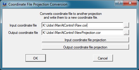
The Coordinate File Project Conversion dialog box
Input coordinate file
Defines the name of the existing coordinate (.cor) file.
Output coordinate file
Defines the name of the output coordinate file.
Input coordinate file projection
Defines or edits the input coordinate file projection. See Coordinate Projections for more information.
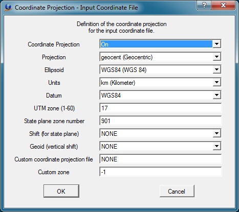
The input coordinate projection definition dialog box
Output coordinate file projection
Defines or edits the output coordinate file projection. See Coordinate Projections for more information.
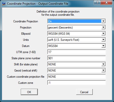
The output coordinate projection definition dialog box
Some points do not have values for all three coordinate axes. The Null Axis Value is an arbitrary figure to which one of a point's 3 coordinate values can be assigned to indicate that it is lacking that value. This value is typically zero, but in cases where zero is a valid coordinate value in the map data, an extreme value like -999 should be used. For example, an elevation-less point could be assigned the coordinates (10, 10, -999) to indicate that it lacks a Z coordinate.
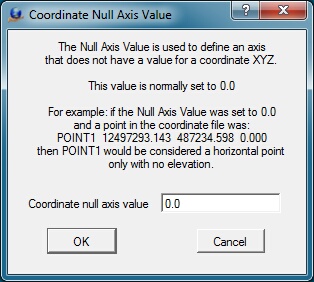
The Null Axis definition dialog box
Project
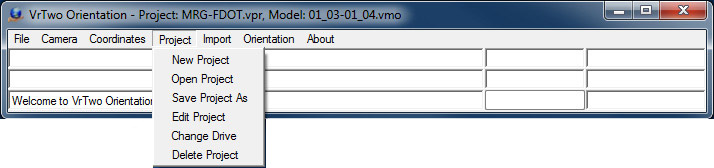
The Project Menu
Manages VrTwo Orientation projects and has the ability to create, open, save, edit and delete projects. Change Drive allows projects to be moved between different drives and folders. The Vr Two Orientation project file name has a .vpr file name extension.
Creates a new project and starts Edit Project.
Opens an existing project. It is not necessary to close the current project before opening another. All current project parameters are saved automatically before another is opened.
Saves the current project with a different file name
Allows editing the current project.
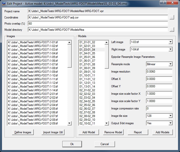
The Edit Project dialog box
Project name
Displays the current project file. This file was created when the project was created in Project -> New Project. The field is for display only and cannot be modified.
Coordinates
The project ground coordinate file may be set in this field by pressing the […] button at the end of the field. When importing orientations from aerial triangulation, this file should contain the coordinates for the pass, tie, and ground control points. A coordinate file of this type is always produced from an aerial triangulation adjustment.
Photo overlap
Defines the approximate photo forward overlap as a percentage. Typical aerial mapping jobs use 60% photo overlap.
Model directory
The model orientation process produces parameter and image files required for stereo display. The Model Directory field defines the target directory (folder) for these files. The files placed in the directory are the epipolar images, the orientation parameter (.orp) files, and the model definition (.vmo) files. Leaving this field blank places these files in the project directory.
Images
Lists the images that are currently in the project and the “Define Images” and “Import Image Util” buttons.
Define Images
Starts the “Define Images” dialog (see below).
Import Image Util
Transfers parameters previously defined in the Vr Image Utility program to this program. The Vr Image Utility project file has a file name extension of .iup.
Models
Displays the currently defined models with model parameters and the Add Model, Remove Model, and Report and Add Models buttons. The active model’s name is highlighted in the list of models. Any model may become active by clicking its model name.
Left image
Displays the current model's left image name. May be changed changed by clicking on the field and selecting a new image from the list.
Right image
Displays the current model's right image name. May be changed changed by clicking on the field and selecting a new image from the list.
Resample mode
Sets the resampling mode to create epipolar images: Nearest Neighbor, Bilinear, or Bicubic. These re-sampling modes affect the quality of the output image and the time it takes to create the epipolar images as follows.
| • | Nearest Neighbor - Fast re-sampling, lowest image quality. High contrast edges appear more jagged. |
| • | Bilinear – Medium re-sampling speed, medium image quality. The image quality is softer than nearest neighbor and is normally acceptable for stereo viewing. |
| • | Bicubic – Slow re-sampling, highest image quality. The image quality is the softest of the three methods. Commonly used to create orthophotos. |
Image resolution
This field specifies the resolution of the epipolar images in millimeters, inches, or pixels as set in the Fiducial Units field in Edit Camera. For example, 12 microns would be entered as 0.012 millimeters. The resolutions of the epipolar images do need to be the same as the original images, though it is recommended. In cases where debugging a stereo model orientation and re-sampling is done multiple times while testing orientation parameters, it is useful to re-sample at a higher resolution such as 30 microns (0.030 millimeters) to obtain a stereo model quickly. “Over sampling” is a process to using a higher image resolution for the epipolar images. This results in a softer image but does not increase the model’s accuracy and increases the size of the epipolar images.
Offset X, Offset Y
Specifies offset to apply to the stereo model viewing center. Offsets are needed in close range photogrammetry when there are high camera angles to the object being photographed. For aerial photogrammetry these values are normally set to zero. See View Relative Orientation 3D under the Orientation pull-down for a 3D graphical display of the image geometry.
Image size scale factor X, Image size scale factor Y
Specifies scale factors to adjust the size of the area covered by the epipolar images. The area re-sampled is based on the Photo Overlap setting. These values are normally set to 1.0 (no scale factor). See View Relative Orientation 3D under the Orientation pull-down for a 3D graphical display of the image geometry.
Add Model
Adds a single model to the list of models. After the model is added, the left and right images must be selected and the epipolar re-sampling image parameters must be set. To check the orientation of the left and right images, go to Orientation -> Relative Orientation to view the left and right images.
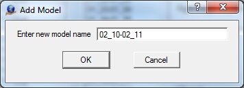
The Add Model dialog box
Delete Model
Deletes the current model from the model list.
Report
Produces a report in a text window about the current file. This report includes project name, image names, and parameters. The contents of this window may be cut and pasted into another document.
Add Models
Forms and adds models in a batch mode based on the images defined in Define Images. The format of the model names is defined in the Model Name Format dialog box. The strip number, left and right numbers and separator characters in the model name can be included. The Update button shows the current format in the upper part of the dialog box based on a strip number of 1 and left and right photo numbers of 2 and 3.
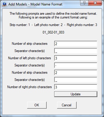
The Model Name Format dialog box for Add Models
Number of strip characters
Defines the number of characters to use for the strip number at the beginning of the model name. Set to blank to disable the output of this field.
Separator character(s)
Sets characters to separate the strip number from the next field. Set to blank to disable output of this field.
Number of left photo characters
Defines the number of characters to use for the left photo number. Set to blank to disable output of this field.
Separator character(s)
Sets characters to separate the left photo characters from the next field.. Set to blank to disable output of this field.
Number of strip characters
Defines the number of characters to use for the strip number. Strip number can be included before the left and right photo numbers. Set to blank to disable output of this field.
Separator character(s)
Sets characters to separate strip characters from the next field. Set to blank to disable output of this field.
Number of right photo characters
Defines the number of characters to use for the right photo number. Set to blank to disable output of this field.
Update
Displays the current format in the upper part of the dialog box based on a strip number of 1 and respective left and right photo numbers of 2 and 3.
The Add Model – Epipolar Re-sampling Parameters
Defines the parameters for creation of epipolar images for stereo viewing.
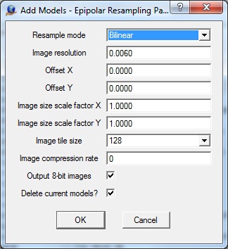
The Epipolar Re-sampling parameters dialog box
Resample mode
Sets the resampling mode to create epipolar images: Nearest Neighbor, Bilinear, or Bicubic. These re-sampling modes affect the quality of the output image and the time it takes to create the epipolar images as follows.
| • | Nearest Neighbor - Fast re-sampling, lowest image quality. High contrast edges appear more jagged. |
| • | Bilinear – Medium re-sampling speed, medium image quality. The image quality is softer than nearest neighbor and is normally acceptable for stereo viewing. |
| • | Bicubic – Slow re-sampling, highest image quality. The image quality is the softest of the three methods. Commonly used to create orthophotos. |
Image resolution
This field specifies the resolution of the epipolar images in millimeters, inches or pixels as set in the Fiducial Units field in Edit Camera. For example, 12 microns would be entered as 0.012 millimeters. The resolutions of the epipolar images do not need to be the same as those of the original images, though using the same resolution is recommended. When debugging a stereo model orientation and re-sampling multiple times while testing orientation parameters, it is useful to re-sample at a higher resolution such as 30 microns (0.030 millimeters) to obtain a stereo model quickly. “Over sampling” is a process which yields a higher image resolution for the epipolar images. This results in a softer image but does not increase the model’s accuracy and increases the size of the epipolar images.
Offset X, Offset Y
Specifies offset values to move the viewing center for the stereo model. These are needed in close range photogrammetry when there are high camera angles to the object being photographed. For aerial photogrammetry, these values are normally set to zero. See View Relative Orientation 3D under the Orientation pull-down for a 3D graphical display of the image geometry.
Image size scale factor X, Image size scale factor Y
Sets scale factors to adjust the size of the area covered by the epipolar images. The area re-sampled is based on the Photo Overlap setting. These values are normally set to 1.0 (no scale factor). See View Relative Orientation 3D under the Orientation pull-down for a 3D graphical display of the image geometry.
Image tile size
Sets the image tile size. Options are "Do Not Tile", 64, 128, 256, 512 and 1024. "Do Not Tile" specifies non-tiled output files. 128 is typically used.
Image compression rate
Defines the JPEG compression rate from 1 to 100. Higher compression ratio values lead to better quality and larger file sizes. Lower compression ratio values mean higher compression, lower quality, and smaller files. A value of 0 indicates no compression.
Output 8-bit images
Specifies whether output epipolar images should use eight bits per sample. If disabled, the bits per sample of the original image will be used.
Delete current models?
Specifies whether to delete the current models. WARNING: Deleting a model will delete its model orientations.
Define Images
The Define Images or Import ImageUtil options identify the images in the project and assign image parameters like photo name format, camera name, strip location, and pixel size to each image. If a project is already set up in Image Utility and interior orientations have already been performed, use the Import ImageUtil option. This reads the list of images from the Image Utility project, and automatically recognizes the image settings and interior orientation.
Selecting Define Image displays a new dialog box, allowing images to be added to the project. Each image has a camera file, strip location, and pixel size. Use this dialog to assign the correct parameters to all images in the project. A camera file must be added to the project from this dialog before any photos can be added to the dialog. It is important that the Strip and Photo Num display correctly beside each image. This is controlled by setting the proper Name Format for the images.
Images may be highlighted in the dialog box by placing the mouse pointer on an image and dragging. Holding shift key and clicking the mouse highlights a range of images. Holding control (Ctrl) key and clicking the mouse highlights additional images.
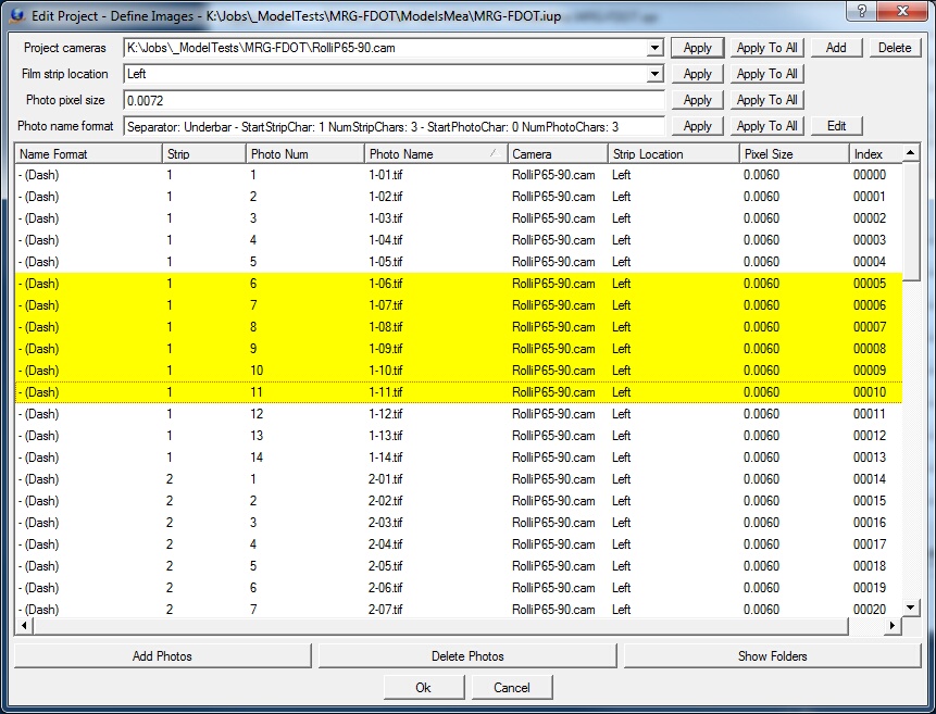
The Edit Project - Define Images dialog box
The first four rows of the dialog box serve as a template to be applied to a group of highlighted images or all images. These first four rows contain the project cameras, film strip location, photo pixel size, and photo name format.
Project cameras
Defines up to 10 project cameras.
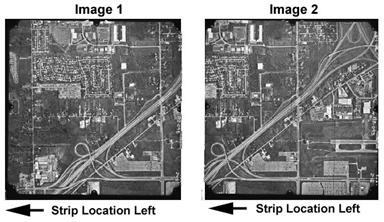
Sets the location of the film strip in reference to the image rotation. Supported film strip locations are Left, Top, Right and Bottom. This parameter is not dependent on the direction of flight, but rather on the orientation of the image as viewed by the user. The following are examples of strip locations
The data strip is to the left, which represents a rotation value of zero. Please see Left and Right Image Rotations for more information.
The model above has been rotated 180 degrees. The strip location is rotated with the images.
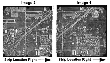
Photo pixel size
Specifies the size of a pixel based on the fiducial coordinate units (millimeteres, inches, or pixels). If the fiducial coordinates are in "pixels", the photo pixel size is always 1.
Photo name format
Describes the method by which to extract image strip and photo number. Please see Photo Name Format for more information.
Defines the new locations for model orientation parameter files when a project is moved to another directory (folder). When this command starts, the user is prompted for an existing VrTwo Orientation parameter (.vpr) file. The new locations for the various model orientation parameter files may be defined in the dialog box shown below.
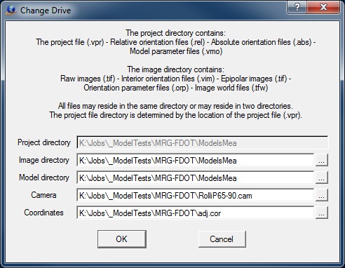
The Change Drive dialog box
Deletes the current project. Before the project is deleted, a warning dialog box is displayed and the user must confirm the delete.
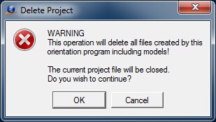
The Delete Project warning dialog box
Import
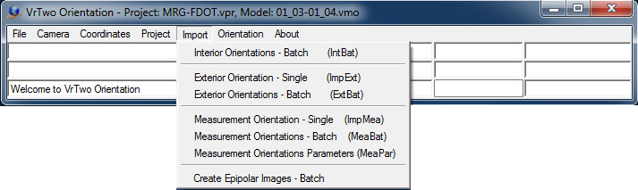
The Import Menu
Import provides methods to orient stereo models from the results of aerial triangulation programs. Interior Orientations can be imported in batch mode. Exterior orientations or measurements can be imported in single model mode or batch.
There are two methods to perform relative and absolute orientations using Import.
Exterior Orientation
Six independent parameters, called the elements of exterior orientation, express the spatial position and angular orientation of a tilted image. The process of aerial triangulation determines these six parameters for each photograph and the availability of these exterior orientations for two overlapping images allows a model setup. The values that make up an exterior orientation are Omega, Phi, Kappa, X, Y, and Z. The Omega, Phi and Kappa are rotations about the x, y, and z axes of the image. X, Y and Z represent the nodal point of the camera lens (where the light rays appear to cross in the camera lens).
Measurements
During aerial triangulation, overlapping and sidelapping images are joined together using pass points (for overlapping images) and tie points (for sidelapping images). Each of these points is placed at a common ground location in the photographs. These points are read for the left and the right images; relative and absolute orientations are performed. Common point names that have an entry in the coordinate file are used during the absolute orientation computations.
Please see Importing Orientations for more information about these two methods and the input formats.
Prerequisites:
The user is expected to know details of the format being imported. The Importing Orientations document should be read before any attempts are made to import model orientations.
Exterior Orientation – Single (ImpExt)
The single model exterior orientation input orients a pair of images into a single model by using the six exterior orientation parameters from the two images.
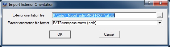
The Import Exterior Orientation initial dialog defining input file and format
Exterior orientation file
Defines the file containing the exterior orientation parameters. This file normally contains the parameters for multiple images, which consist of an entire job or a single aerial triangulation bundle adjustment. Please refer to the document Importing Orientations for more information on the various formats.
Exterior orientation file format
Specifies the format of the file selected in the Exterior orientation file field.
Many of the orientation file formats require additional information about the strip and photo numbers. This information defines the conversion of photo names to strip and photo numbers.
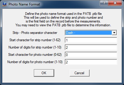
The Photo Name Format dialog. Defines photo names to strip and photo number conversion parameters.
The Photo Name Format dialog box defines the format for decoding the strip number and photo number from and image file name. Please see Photo Name Format for more information about these parameters.
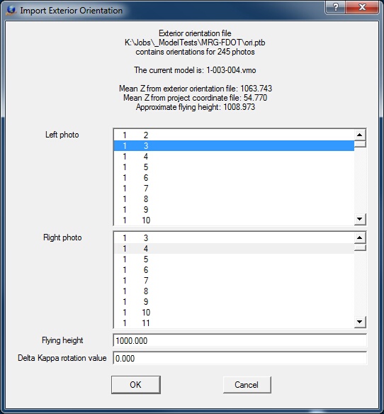
The Import Exterior Orientation left and right photo definition dialog
Select the two images to orient in the Left photo and Right photo menus. The exterior orientation file and number of images read is shown along with the current model at the top of the dialog box.
Flying Height
Specifies in ground units the flying height, the approximate distance between the ground/object and the camera. An approximate value, computed from the mean camera elevations of the exterior orientation file and the mean ground elevation from the active ground control file, is displayed in the information area of the dialog box.
Delta Kappa Rotation Value
Specifies a Kappa rotation angle (about the Z axis) in the exterior orientation file. This is required if the images were rotated from the positions that were used in the aerial triangulation program. It is suggested that an angle of zero is first attempted. If the import does not produce a viewable stereo model, a rotation value of 180 should be entered. The possible rotation values are 0, 90, 180, and 270 degrees.
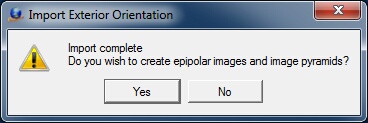
Creation of epipolar images and image pyramids conformation dialog.
When the import is complete, a dialog box will display asking if epipolar images should be created. Press "Yes" to start generating epipolar images for stereo viewing. Press "No" to skip generation of epipolar images.s
When the import of a model using exterior orientation is complete, the VrTwo Orientation program may be exited and VrTwo started to view the model.
Exterior Orientations – Batch (ExtBat)
Many stereo models can be oriented using exterior orientations with Exterior Orientations Batch. Before Exterior Orientations Batch can run, the project must be set, the models must be defined, and interior orientations must be complete.
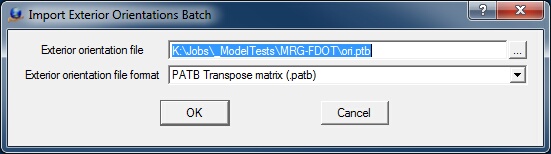
The Import Exterior Orientations initial dialog defining input file and format
Exterior Orientation File
Defines the file that contains the exterior orientation parameters. This file normally contains the parameters for multiple images, be they an entire job or a single aerial triangulation bundle adjustment. Please refer to the document Importing Orientations for more information.
Exterior Orientation File Format
Specifies the format of the file defined above in "Exterior orientation file".
Depending on the Interior Orientation File Format selected, one or more additional dialog boxes may appear to request more information about the input format. One of these dialog boxes may request information about the Photo Name Format. The "Photo Name Format" dialog box determines how to decode the strip and photo numbers from the image file name.
If ISAT is selected as the Interior Orientation File Format, the following dialog box will be displayed.
If the Strip Number Location for the ISAT ‘photo’ file was specified as “Embedded with the photo number” then the following dialog box will be displayed.
The Photo Name Format dialog. Defines photo names to strip and photo number conversion parameters.
The Photo Name Format dialog box determines how to decode the strip and photo numbers from the image file name. Please see Photo Name Format for more information a
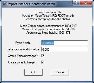
Import Exterior Orientations parameters dialog
Flying Height
Specifies in ground units the flying height, the approximate distance between the ground/object and the camera. An approximate value, computed from the mean camera elevations of the exterior orientation file and the mean ground elevation from the active ground control file, is displayed in the information area of the dialog box.
Delta Kappa Rotation Value
Specifies a Kappa rotation angle (about the Z axis) in the exterior orientation file. This is required if the images were rotated from the positions that were used in the aerial triangulation program. It is suggested that an angle of zero is first attempted. If the import does not produce a viewable stereo model, a rotation value of 180 should be entered. The possible rotation values are 0, 90, 180, and 270 degrees.
Create Epipolar Images?
Specifies whether to create epipolar images after each model has been set up.
Create pyramid images?
Specifies whether to create image pyramids of the epipolar images after each model has been set up.
A list of models available for orientation is displayed.
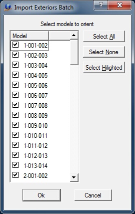
The selection of models for import dialog
Afterhe import completes, its results are placed in the information dialog box. 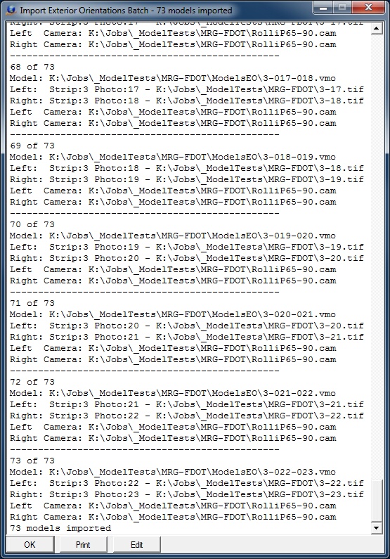
The import exterior orientations batch information box
Measurement Orientation – Single
The single model measurement orientation orients a pair of images into a single model using common measured points from the two images. These points are typically measured in an aerial triangulation program.
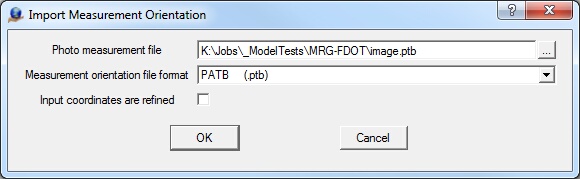
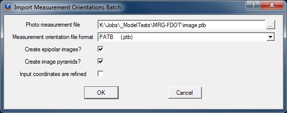
The Import Measurement Orientations initial dialog defining input file and format
Photo measurement file
Defines the file that contains the photo measurements. This file normally contains the parameters for multiple images, whether they consist of an entire job or a single aerial triangulation bundle adjustment. Please refer to the document Importing Orientations for more information.
Measurement orientation file format
Specifies the format of the file selected in the "Exterior orientation file" field.
Input coordinates are refined
When measurements are imported, they typically are unrefined coordinates; they do not have the camera distortion corrections applied. If this option is checked, it is assumed that input coordinates are refined and will be converted to unrefined coordinates before passing them to the relative orientation solution. (default = unchecked)
Once a measurement input format is selected, a dialog box prompts for additional file format parameters. These parameters include the photo measurement file name and the coordinate units.
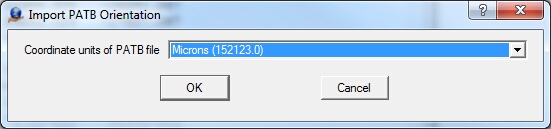
The definition of coordinate units as microns or millimeters dialog
Coordinate units of input file
Specifies coordinate units for the input file (millimeters or microns). The user may need to view the input file in a text editor to determine the value for this parameter. Most photo coordinate systems are in millimeters so an x, y coordinate of -26.499567, 2.2979591 would indicate millimeters while an x, y coordinate of -26499567.0, 22979591.0 would indicate microns.
Some formats require more information.
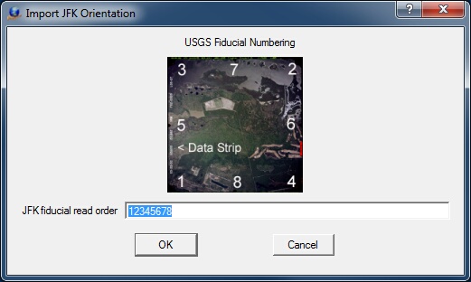
Definition of the JFK fiducial read order dialog
JFK fiducial read order
When reading the interior orientations using the JFK aerial triangulation software, the operator may read the fiducials in any order. The order used by the aerial triangulation operator must be known and entered in the field. If only four fiducials were observed (not recommended)n the unused fiducials are entered with a value of zero. For example: 12340000.
The left and right image names are selected in the next step.
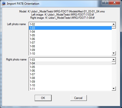
The Import Measurements Orientation left and right photo definition dialog
After the left and right images are selectedn the measurements are imported and the relative and absolute orientations are computed. The results are shown in the information dialog box.
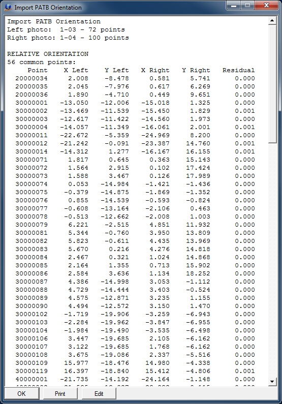
The import measurements orientations information box
When the model import is complete, the results of the import may be viewed in Orientation -> Relative Orientation and Orientation -> Absolute Orientation.
Measurement Orientations – Batch (MeaBat)
It is possible to orientate many stereo models using measurement orientations with Measurement Orientations Batch. Before Measurement Orientations Batch can be run, the project must be set, the models must be defined and interior orientations must be complete.
The Import Measurement Orientations initial dialog defining input file and format
Photo measurement file
Defines the measurement parameter file name. It is typical for the measurements for many images to be in a single input file.
Measurement orientation file format
Specifies the format of the file selected in the "Photo measurement file" field.
Create Epipolar Images?
Specifies whether to create epipolar images after each model has been set up.
Create pyramid images?
Specifies whether to create image pyramids of the epipolar images after each model has been set up.
Input coordinates are refined
When measurements are imported, they typically are unrefined coordinates; they do not have the camera distortion corrections applied. If this option is checked, it is assumed the input coordinates are refined and will be converted to unrefined coordinates before passing them to the relative orientation solution. (default = unchecked)
Depending on the orientation file format selected, one of the following dialog boxes may appear to request more information about the input format:
ISAT
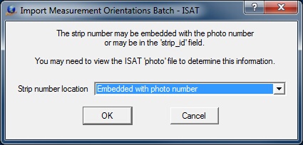
The ISAT Strip Number Location dialog box. Displayed when importing ISAT measurement orientations.
Strip number location
In the ISAT photo file there are two possible locations in which the strip number may be stored. These locations are:
| • | Embedded with the photo number – The strip number is part of the photo name following the ‘photo_parameters’ keyword. For example, the record: |
begin photo_parameters 205 strip_id 2
would assume the strip number and photo number to be included in the 205 field and the 2 after the strip_id would be ignored. If the number of strip characters was 1 and the number of photo characters was 2 then strip 2, photo 5 would be decoded from the 205 field.
| • | After the ‘strip_id’ keyword – The strip number follows the ‘strip_id’ keyword which is on the same record as the ‘photo_parameters’ keyword. For example, the record |
begin photo_parameters 101 strip_id 3
would assume the photo number as 101 and the strip number as 3.
ATLAS, ISSBA, ORIMA, PATB, VRAT
The Photo Name Format dialog. Defines photo names to strip and photo number conversion parameters.
The Photo Name Format dialog box defines the format for decoding the strip number and photo number from and image file name. Please see Photo Name Format for more information about these parameters.
PATB
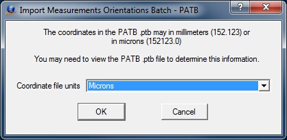
The definition of coordinate units as microns or millimeters dialog
Coordinate file units
The coordinates that represent the photo measurements in the input file may expressed in millimeters or microns. The user may need to view the input file in a text editor to determine the value for this parameter. Most photo coordinate systems are in millimeters so an x, y coordinate of -26.499567, 2.2979591 would indicate millimeters while an x, y coordinate of -26499567.0, 22979591.0 would indicate microns.
A list of model available for orientation is displayed and all models or selected models may be chosen for setup.
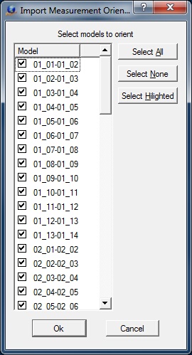
The selection of models for import dialog
After completion of import the results of the import are placed into the information dialog box.
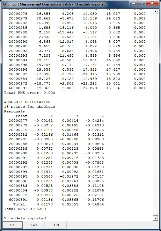
The import exterior orientations information box
When the model import is complete and epipolar images have been created the results of the import may be viewed in Orientation -> Relative Orientation and Orientation -> Absolute Orientation.
Measurement Orientation Parameters (MeaPar)
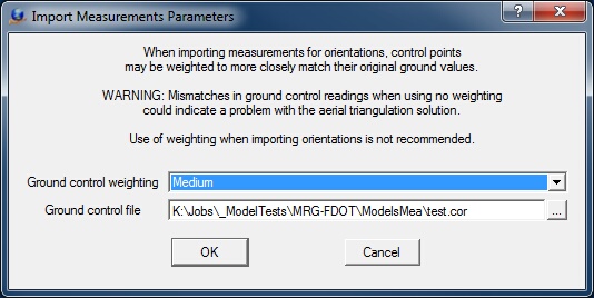
Measurement Orientation Parameters Dialog
When importing measurements for orientations, control points may be weighted to more closely match their original ground values.
WARNING: Mismatches in ground control readings when using no weighting could indicate a problem with the aerial triangulation solution or the ground control used in the aerial triangulation solution. The use of weighting when importing orientations is not recommended.
Ground control weighting
Specifies the amount of ground control point weighting. Options include None, Low, Medium or High. The recommended setting for this parameter is None.
Ground control file
The ground control file that is specified in Coordinates field in Edit Project typically contains the original ground control (field surveyed) and pass a tie points from the aerial triangulation solution. A second ground control file is requited so the original ground control (field surveyed) points can be identified in the weighting process. The file specified should contain only the original ground control points without the pass and tie points.
Create Epipolar Images – Batch (CreEpi)
In many of the orientation methods the creation of epipolar images may be skipped. Create Epipolar Images creates these images in a batch mode.
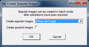
Create Epipolar Images dialog
Create epipolar images
This parameter sets the creation mode for the epipolar images. Options are “If they don’t exist” and “Create all epipolar images”.
Create pyramid images?
Checking this parameter will create image pyramids of the epipolar images after the epipolar images have been created.
Orientation
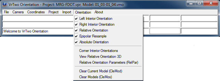
The Orientation Menu
Left, Right Interior Orientation (LefInt) (RigInt)
There are four methods of performing interior orientations in Vr Mapping. The auto correlated automatic interior orientation process is available in the Vr Image Utility (imageutill.exe) program, importing interior orientations or manually reading the fiducials and Corner Interior Orientations for images that do not contain fiducial markings. The Left / Right Interior Orientation is the manual method. A project must be set up and the camera calibration file must be defined before starting this command.
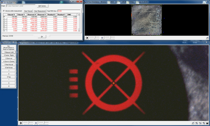
Interior Orientation Interactive Dialog
There are four windows or dialog boxes that make up the interior orientation application.
Residuals – This is the dialog box in the upper left corner of the screen. The Residuals dialog box shows the current residuals of the adjustment. After the third fiducial is read the image pixel size is shown in the lower left corner of this dialog.
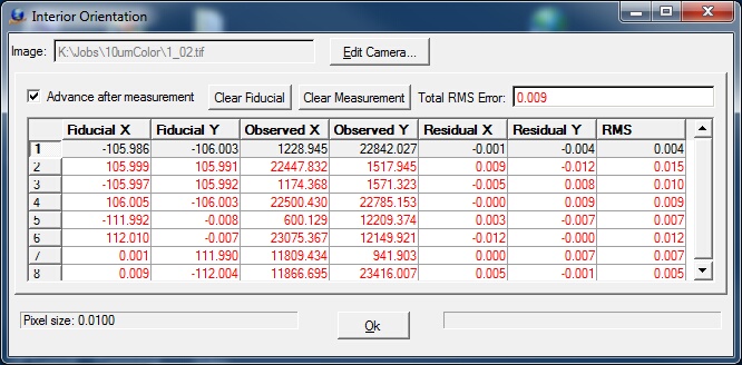
The Interior Orientation results dialog
To drive to a fiducial point the point number may be selected with the mouse.
Overview – The overview window is in the upper right corner of the screen and shows the entire image. If the cursor is moved into this window the shape of the cursor will change to a square and a press of the left mouse button will display that portion of the image in the measurement window below.
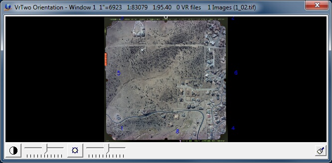
The Interior Orientation overview window
The fiducial numbers are displayed in the overview window.
Measurement – This window displays an enlarged area of the image and allows the observations of fiducials. The controls for the measurement window are displayed in the Menu Keys dialog box to the left.
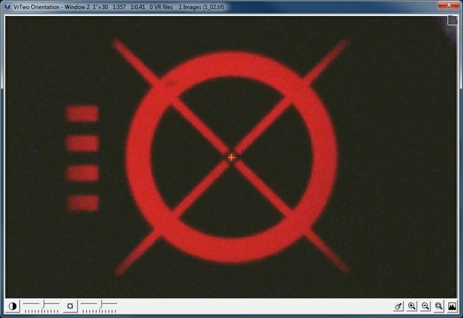
The Interior Orientation measurement window
Fiducials are measured by pressing the left mouse button. See Menu Keys below for all the display controls.
Menu Keys – The display and measurement controls for the measurement window are displayed in the Menu Keys dialog box. Several buttons on the menu keys are mapped onto the mouse and all buttons may be used by pressing the corresponding Fkeys on the system keyboard. For example; to zoom out the F3 key on the system keyboard may be pressed. Note that the buttons cannot be pressed with mouse clicks.
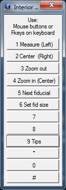
The Interior Orientation Menu Keys dialog
1 Measure (Left)
Measurement button for fiducial observations. This is mapped to the left mouse button.
2 Center (Right )
Centers the screen at the current cursor location. This is mapped to the right mouse button.
3 Zoom out
Zoom out using the zoom scale factor specified in Preferences.
4 Zoom in (Center)
Zooms in using the zoom scale factor specified in Preferences. This is mapped to the center wheel button on the mouse.
5 Next fiducial
Advances to the next fiducial.
6 Set fid size
Sets the fiducial size by digitizing lower left and upper right points around the fiducial. The value is used to set the Fiducial size in the camera calibration which is used for Automatic Interior Orientations in the Vr Image Utility (imageutil.exe) program.
9 Tips
Displays several helpful tips.
The relative orientation command performs manual relative orientations with one of three options when reading points.
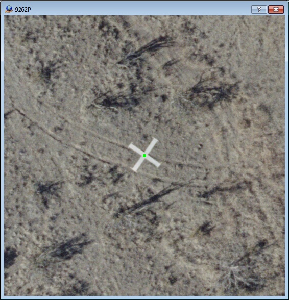
| • | Mono-comparator mode – A common point is read in the left image and the right image. This is useful when reading photo identifiable items such control point panels. |
| • | Autocorrelation assist – The cursor is positioned on one image and the common location is found on the other. The cursor may be positioned in the left or right image. |
| • | Stereo – The two images may be displayed in stereo and parallax may be cleared using a method similar to clearing parallax on analytical instruments. |
After completion of relative orientation, epipolar images may be created which will produce a viewable stereo model.
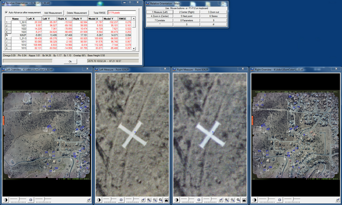
The Relative Orientation interactive measurement environment
There are six windows or dialog boxes that are displayed during relative orientation.
Residuals – This is the dialog box in the upper left corner of the screen. The Residuals dialog box shows the current residuals of the adjustment.
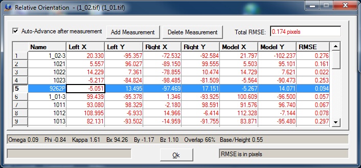
The Relative Orientation interactive measurement control and results dialog
Any point may be driven to by clicking on its sequence number. A least six points must be read before a solution will be computed. To add a measurement the Add Measurement button should be pressed first then the points should be located on the images.
Menu Keys – The display and measurement controls for the measurement window are displayed in the Menu Keys dialog box. Several buttons on the menu keys are mapped onto the mouse and all buttons may be used by pressing the corresponding Fkeys on the system keyboard. For example; to zoom out the F3 key on the system keyboard may be pressed. Note that the buttons cannot be pressed with mouse clicks.
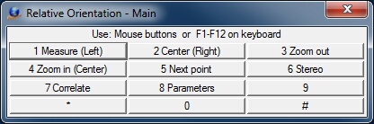
The Relative Orientation interactive measurement Menu Keys dialog
1 Measure (Left)
Measurement button for fiducial observations. This is mapped to the left mouse button.
2 Center (Right )
Centers the screen at the current cursor location. This is mapped to the right mouse button.
3 Zoom out
Zooms out using the zoom scale factor specified in Preferences.
4 Zoom in (Center)
Zooms in using the zoom scale factor specified in Preferences. This is mapped to the center wheel button on the mouse.
5 Next fiducial
Advances to the next fiducial.
6 Stereo
Changes the measurement mode to stereo. See Relative Orientation Stereo Window.
7 Correlate
Finds the common point in the other image based on cursor position in the left or right measurement window. The result of the correlation is displayed in the Residual and Menu Keys dialog boxes. This result may be rejected or accepted. Point correlation is relayed as a number from 0-1. Guidelines for correlation interpretation are as follow
| • | 0.9 to 1.0 – Very good |
| • | 0.8 to 0.9 – Good |
| • | 0.7 to 0.8 – Fair |
| • | 0.7 and below – Poor (result should be rejected). |
Overview and Measurement Windows – The four windows along the bottom of the screen are the overview (1) and measurement (2) windows. If the cursor moves into one of the overview windows, the cursor changes to a square. Pressing the right mouse button in one of the overview windows copies an enlarged area of the image to the corresponding measurement window.
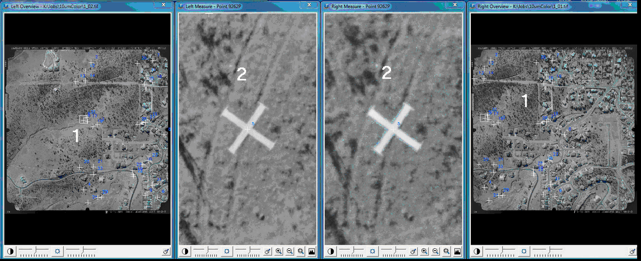
The Relative Orientation interactive measurement left and right overview and measurement windows
Relative Orientation Stereo Window
The Relative Orientation stereo window
Pressing MenuKeys button 6 in relative orientation switches measurement mode to stereo and clears the parallax at the point of interest.
The following controls are available in stereo:
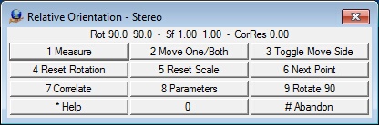
The Relative Orientation stereo Menu Keys
1 Measure
Measures the point in stereo and records the position on both images.
2 Move One/Both
Toggles the movement of the images from both moving to one moving. When the mode is set to one image moving then parallax can be cleared at that location.
3 Toggle Move Side
Toggles the image side while clearing the parallax.
4 Reset Rotation
Resets the current image rotation. See Rotating One Image below.
5 Reset Scale
Resets the current image scale to 1.0. See Scaling One Image below.
6 Next Point
Advances to the next point in relative orientation
7 Correlate
Locates a common point in the images.
8 Parameters
Allows setting stereo parameters.
9 Rotate 90
Rotates both images 90 degrees. This is useful to view stereo between strips because side by side overlap does not produce viewable stereo in this situation.
* Help
Displays help on additional key sequences for viewing features. The * keys is F10 on the system keyboard.
# Abandon
Quits stereo mode and returns to the previous relative orientation layout.
Additional Features and Controls When in Stereo Mode
| • | Changing the Cursor Color – Roll the mouse wheel to change between cursor colors (green, red, black, white, yellow or blue). |
| • | Changing the Cursor Size – Press and hold "Alt" and roll the mouse wheel. |
| • | Rotating One Image – Press and hold "Shift" and move the mouse in the Y plane. This is useful when viewing images with high rotation angles (as occurs in images from two different strips/flight lines). This adjustment makes stereo viewing more comfortable in these situations. This motion is similar to the “Squint knob” or “Dove prisms” on analytical stereo plotters. |
| • | Scaling One Image – Press and hold "Ctrl" and move the mouse in the Y plane. This is useful when viewing two images with different scales (as occurs in images from two different strips/flight lines). This adjustment makes stereo viewing more comfortable in these situations. This motion is similar to the independent zoom controls found on many analytical stereo plotters. |
| • | Zoom Up – Press "Page Up". Also known as Zoom Out. |
| • | Zoom Down – Press "Page Down". Also known as Zoom In. |
| • | Center Images – Press "Home" to center both images at the current cursor location. |
| • | Load More Image – Two image patches are used for stereo viewing. The edges of these image patches can be reached if the cursor moves great distances in the X or Y planes. Press "Home" on the system keyboard to load more image data around the current cursor location. |
| • | Disengage Cursor – Press "Insert" on the system keyboard to disengage the stereo cursor, allowing operations to be performed with the mouse. Press the Insert key again to re-engage the stereo cursor. |
Creates epipolar images of the current model. This step is normally included in the orientation process after relative orientation but may be used here if the step was skipped earlier.
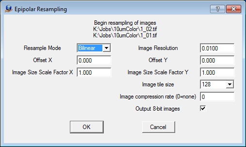
The Epipolar Resampling parameter definition dialog
Resample mode
Sets the resampling mode to create epipolar images: Nearest Neighbor, Bilinear, or Bicubic. These re-sampling modes affect the quality of the output image and the time it takes to create the epipolar images as follows.
| • | Nearest Neighbor - Fast re-sampling, lowest image quality. High contrast edges appear more jagged. |
| • | Bilinear – Medium re-sampling speed, medium image quality. The image quality is softer than nearest neighbor and is normally acceptable for stereo viewing. |
| • | Bicubic – Slow re-sampling, highest image quality. The image quality is the softest of the three methods. Commonly used to create orthophotos. |
Image resolution
This field specifies the resolution of the epipolar images in millimeters, inches, or pixels as set in the Fiducial Units field in Edit Camera. For example, 12 microns would be entered as 0.012 millimeters. The resolutions of the epipolar images do need to be the same as the original images, though it is recommended. In cases where debugging a stereo model orientation and re-sampling is done multiple times while testing orientation parameters, it is useful to re-sample at a higher resolution such as 30 microns (0.030 millimeters) to obtain a stereo model quickly. “Over sampling” is a process to using a higher image resolution for the epipolar images. This results in a softer image but does not increase the model’s accuracy and increases the size of the epipolar images.
Offset X, Offset Y
Sets the values by which to move the viewing center for the stereo model. Offsets are needed in close range photogrammetry due to high camera angles to the object being photographed. For aerial photogrammetry, these values are typically set to zero. See View Relative Orientation 3D under the Orientation pull-down for a 3D graphical display of the image geometry.
Image size scale factor X, Image size scale factor Y
Sets the scale factors used to adjust the size of the area covered by the epipolar images. The area to be re-sampled is determined by the Photo Overlap setting. However, enlargement is sometimes necessary. These values are normally set to 1.0 (no scale factor). See View Relative Orientation 3D under the Orientation pull-down for a 3D graphical display of the image geometry.
Image tile size
Defines the epipolar image tile size. Options are "Do Not Tile", 64, 128, 256, 512, and 1024. Option "Do Not Tile" specifies non-tiled output files. 128 is the default.
Image compression rate (0=none)
Defines the JPEG compression rate from 1 to 100. Higher values lead to higher quality and larger file size. Lower values lead to lower quality and smaller files. A value of 0 indicates no compression.
Output 8-bit images
Specifies whether the output epipolar images will use eight bits per sample. If unchecked, the bits per sample of the original image will be used.
After interior and relative orientations have been completed and epipolar images have been generated, a viewable stereo model is produced. Next, the model must be tied to a known ground control system. This is the "absolute orientation" of the model. To perform manual absolute orientation, at least three elevations and two horizontal positions must be known for photo identifiable positions in the model area.
NOTE: The absolute orientation stereo window is a static image window. The images are stationary below a moving cursor. The cursor may be well above or below the model surface. Using the "Home" key on the system keyboard can better the situation by placing the cursor at the same elevation as the window frame. Alternately, pressing "Mean Z" (MenuKeys button 6) drives the elevation to the average model elevation.
When driving the cursor to the ground surface using the wheel on the system mouse, hold "Shift" on the system keyboard to apply a x4 multiplier to Z movement.
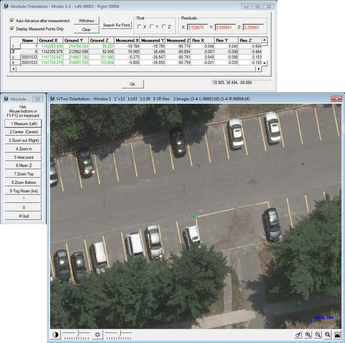
The Absolute Orientation interactive measurement environment
Three windows or dialog boxes are displayed during relative orientation.
Residuals – Displayed in the upper left corner. Shows the current residuals of the adjustment.
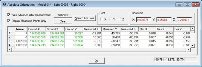
The Absolute Orientation interactive measurement control and results dialog
Drive to any point by clicking its sequence number. An axis from any point in the adjustment may be floated or taken out of the absolute orientation solution by driving to the point then checking its Float axis.
Menu Keys – Displays measurement controls. Buttons may be mapped to the mouse. Buttons may be engaged using their corresponding Function keys on the system keyboard (i.e. F3 to engage "Zoom out").
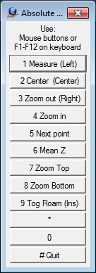
The Absolute Orientation Menu Keys
1 Measure (Left)
Measures absolute orientation observations. This is mapped to the left mouse button.
2 Center (Center)
Centers the screen at the current cursor location. This is mapped to the center wheel on the mouse. The Home key on the system keyboard performs the same function.
3 Zoom out (Right)
Zooms out using the zoom scale factor specified in Preferences. This is mapped to the right mouse button. The Page Up key on the system keyboard performs the same function but zooms out at 2x increments.
4 Zoom in
Zooms in using the zoom scale factor specified in Preferences. The Page Down key on the system keyboard performs the same function but zooms in at 2x increments.
5 Next fiducial
Advances to the next fiducial.
6 Mean Z
Drives the elevation of the cursor to the average elevation of the model's control points. This can make it easier to place the Z in a reasonable location if the cursor is well above or below the model surface.
Measurement Window
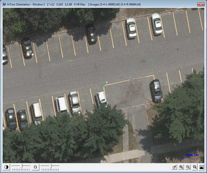
The Absolute Orientation interactive stereo measurement window
Three-dimensional view window used to measure control points.
Corner Interior Orientations (CorInt)
Computes the interior orientations of the current model images using their corners. This can be used to establish a generic interior orientation for images without fiducials or camera calibrations.When using this format, the Import orientation file parameter does not need to be defined.
NOTE: Corner Interior Orientations automatically sets the photo size in the current camera calibration definition (.cam) using the photo pixel size defined in Project -> Edit Project -> Define Images.
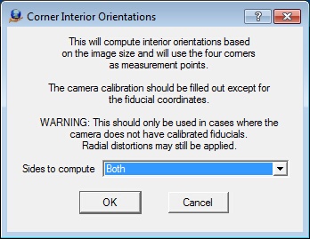
The Corner Interior Orientations dialog
Sides to compute
Defines the sides to compute (Both, Left, or Right).
View Relative Orientation 3D (VieRel)
Views the geometry of the stereo model and its interactions with the two images, focal lengths, the model areas, and the image angles and projections. This is useful to view stereo geometry for close range applications. Omega, Phi and Kappa angles in degrees, the Bx, By and Bz shifts in Fiducial Units, and the photo overlap are shown. Refer to File -> Preferences for preference parameters for the Relative Orientation 3D window.
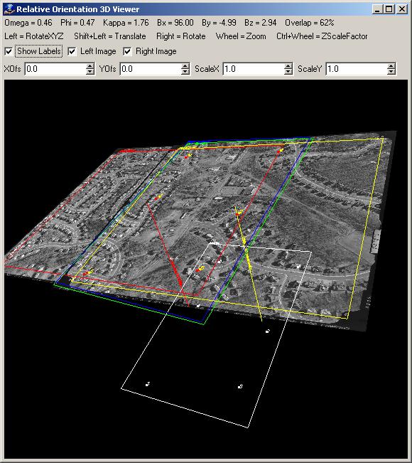
The Relative Orientation 3D Viewer
XOfs, YOfs
Graphically show the x and y offsets of the images to the stereo model plane. The stereo model plane is shown as a white rectangle. The offset values move the viewing center for the stereo model. This is necessary in close range photogrammetry, in which there are high camera angles to the object being photographed. For aerial photogrammetry, these values are normally set to zero.
ScaleX, ScaleY
Graphically show the x and y scale factors of the images to the stereo model plane. These scale factors adjust the size of the area covered by the epipolar images. The area to be resampled is based on the Photo Overlap setting, but enlarging the image is sometimes required. These values are typically set to 1.0 (no scale factor).
Controls to rotate and manipulate the viewing of the 3D model are:
| • | Rotate XYZ - Press and hold the left mouse button to rotate the model about the X, Y and Z axis. |
| • | Translate XY - Press and hold the Shift key on the system keyboard and the left mouse button to translate the model in the X and Y directions. |
| • | Rotate XY – Press and hold the right mouse button to rotate the model about the view XY axis. |
| • | Zoom – Rotate the mouse wheel to zoom in and out on the model. |
| • | Fast Zoom – Press and hold the shift key on the system keyboard and rotate the mouse wheel to fast zoom in and out on the model |
| • | Z Scale Factor – Press and hold the control (Ctrl) key on the system keyboard and rotate the mouse wheel to change the Z scale factor of the model. |
Relative Orientation Parameters (RelPar)
Defines parameters used in the relative orientation solution.
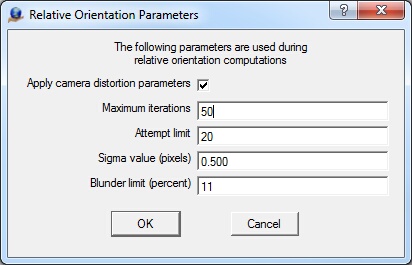
Relative Orientation Parameters
Apply camera distortion parameters
Determines whether to solve the relative orientation using refined (pinhole) coordinates. (default = checked)
Maximum iterations
Specifies the maximum number of iterations when seeking a solution. (default = 50)
Attempt limit
Specifies the maximum number of attempts to find new/better solutions using different initial data sets. (default = 20)
Sigma value (pixels)
Specifies image measurement start deviation in pixels. (default = 0.5)
Blunder limit (percent)
Defines the maximum blunder point percentage in an acceptable solution. For example, a value of 11 (11%) would allow approximately one blunder point for every 10 points in the relative orientation adjustment. The range for this parameter is 0 to 100. [default = 11 (11%)]
Clears all or part of the steps used in model orientation for the current model.
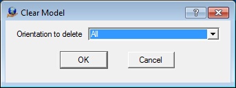
The Clear Model orientation dialog
Orientation to delete
Deletes orientation steps.
The About Menu
Displays this VrTwo Orientation help document
Displays the release notes that were delivered with the current release
Displays the release notes from the Vr Mapping Software web site (www.cardinalsystems.net/help5/ReleaseNotes.html)
Displays the current software version.
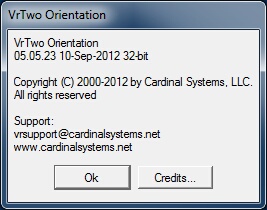
The About dialog showing version information
Left and Right Image Rotations
The two images that make up a stereo model may be in one of several supported rotation configurations. Images may be rotated 0, 90, 180 or 270 degrees, corresponding with strip locations of left, top, right and bottom. Images may be in normal or pseudo-overlap configurations and the stereo direction between image overlaps may in the X and/or Y directions.
When entering parameters for a camera calibration (.cam) file, the values should be entered with the strip direction to the left (0 degree rotation). These values would include the image size and the Calibrated Principal Point values. If rotated images are used to set stereo models, the camera values are defined with the strip location to the left. Image rotations are defined in Edit Project -> Define Images -> Strip Location. Projects may use multiple image rotation configurations but only a single camera calibration file.
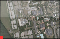
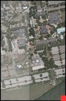
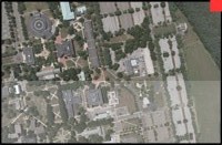
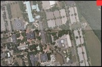
The following are examples of rotations for the left and right images and the resulting stereo model. A red square denotes the lower left corner of the un-rotated (strip location left) image. The examples below indicate most of the common rotations but do not show all the available combinations for image rotations. The unshaded area in each image shows the side that is displayed in stereo.
The model comes from an aerial triangulation solution. The stereo overlap was performed in the Y direction. The camera system used for this example produces un-rotated images with a longer X axis. Please refer to the project camera calibration report to determine the zero rotation (strip location left) orientations of the images for your project.
Left image: 3 - Right image: 4
Left strip location: Left / 0 degrees Right strip location: Left / 0 degrees Stereo overlap: -Y / down |
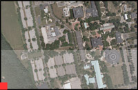
Resulting Stereo Model
Stereo orientation: Normal
|
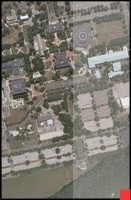
Left image: 3 - Right image: 4
Left strip location: Top / 90 degrees Right strip location: Top / 90 degrees Stereo overlap: X Pseudo
|
Resulting Stereo Model
Stereo orientation: Pseudo |
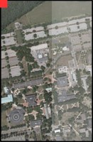
Left image: 3 - Right image: 4
Left strip location: Right / 180 degrees Right strip location: Right / 180 degrees Stereo overlap: +Y / up
|
Resulting Stereo Model
Stereo orientation: Pseudo
|
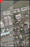
Left image: 3 - Right image: 4
Left strip location: Bottom / 270 degrees Right strip location: Bottom / 270 degrees Stereo overlap: X Normal
|
Resulting Stereo Model
Stereo orientation: Normal |
Left image: 3 - Right image: 4
Left strip location: Left / 0 degrees Right strip location: Top / 90 degrees Stereo overlap: X and Y
|
Resulting Stereo Model
Stereo orientation: Normal |
Left image: 4 - Right image 3
Left strip location: Top / 90 degrees Right strip location: Left / 0 degrees Stereo overlap: X and Y
|
Resulting Stereo Model
Stereo orientation: Normal |
Vr Mapping Coordinate File Format
The Vr Mapping coordinate file (.cor) comprises a header and a list of point names, coordinates and optional weights. Fields may be arranged in several different orders. The coordinate file is an ASCII file and may be viewed with any text editor. Documentation about the file format is included in each file header. The following is a typical Vr Mapping coordinate file.
# Coordinate File
# Layout - Field Order Min number of fields
# 0 NAME X Y Z CX CY CZ 3
# 1 NAME Y X Z CY CX CZ 3
# 2 X Y Z NAME CX CY CZ 4
# 3 Y X Z NAME CY CX CZ 4
# 4 NAME X Y Z 3
# 5 NAME Y X Z 3
# 6 X Y Z NAME 4
# 7 Y X Z NAME 4
# 8 X Y NAME 3
# 9 Y X NAME 3
#
# Format - Coordinate format
# 0 State plane
# 1 UTM
# 2 Geographic Decimal Degrees
#
# SpZone - State plane zone
#
# Datum - Datum
# 0 NAD1927
# 1 NAD1983
#
# UtmZone - UTM Zone
# 1-60 UTM zone number
#
# Units - Coordinate units
# 0 Us Foot
# 1 International Foot
# 2 Meters
# 3 Inches
# 4 Pixels
#
Layout 4
Format 0
SpZone 901
Datum 0
UtmZone 17
Units 0
#
201 837831.194130 951352.037020 303.8200
202 836399.079330 951266.642540 337.6800
203 837994.618340 950634.951710 299.6000
204 836711.670600 950565.198920 326.3200
205 836018.411470 950724.804370 309.2900
Any record starting with a # symbol is considered a comment. The Layout is the most important keyword in the file as it specifies the order of the fields.
Importing a File to Use as a Vr Mapping Coordinate (.cor) File
Any ASCII file in the following format may be read by Vr Mapping. The file must have a .cor file name extension and the fields must be separated by one or more blanks or tabs. The following is an ASCII file that would be acceptable for use by Vr Mapping. It is formatted as point name followed by X, Y, and Z.
35 1410993.867000 667652.883000 268.0300
36 1421351.907000 670064.772000 251.8240
37 1432756.960000 660002.435000 438.6740
38 1426080.595000 651648.623000 417.5070
39 1437426.118000 648649.673000 256.5350
99999 1440539.957000 647417.838000 241.1880
2727011 1410534.575000 658885.235000 294.5090
2727012 1412335.275000 659061.598000 280.9620
2727021 1410279.378000 661225.872000 260.6650
2727022 1412458.095000 661055.148000 284.6200
2727023 1413884.366000 661259.361000 425.0660
2727031 1410433.453000 663554.024000 267.3830
2727032 1412556.566000 663154.921000 244.1890
2727033 1414464.428000 663015.598000 460.9970
Processes like aerial triangulation and model orientation use image strip and photo number. These numbers are typically encoded in the image file name. Photo Name Format describes the method for extracting this information.
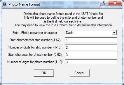
The Photo Name Format dialog
Photo Name formatting parameters are Strip-Photo separator character, start character for the strip number, number of digits for the strip number, start character for the photo number, and number of digits for the photo number. If the separator character is used to describe the format, no further parameters are needed. If the file name does not have a separator character, the start character and number of characters must be used.
The photo separator character may be Underbar ‘_’, Dash ‘-‘, or Tilde (~). The following are several examples of the Photo Name Format:
Photo name: 23-56.tif
Photo separator character: Dash
Start character for strip number: any
Number of digits for strip number: any
Start character for photo number: any
Number of digits for photo number: any
Strip number: 23
Photo number: 56
Photo file name: 23056.tif
Photo separator character: None
Start character for strip number: 1
Number of digits for strip number: 2
Start character for photo number: 3
Number of digits for photo number: 3
Strip number: 23
Photo number: 56
Photo file name: 23056.tif
Photo separator character: None
Start character for strip number: 1
Number of digits for strip number: 3
Start character for photo number: 4
Number of digits for photo number: 2
Strip number: 230
Photo number 56