Vr Mapping |
ON-LINE REFERENCE DOCUMENTATION CARDINAL SYSTEMS, LLC |
Vr Aerial Triangulation (VrAirTrig)
Type: Stand-alone application (vrat.exe)
Aerial triangulation measurement and optional adjustment application.
See also: Tutorial Vr Aerial Triangulation
The VrAirTrig with the Layout environment
Convert Coordinate File (ConCoo)
Check for New Version (CheVer)
Vr Mapping Coordinate File Format
Vr Aerial Triangulation (VrAirTrig) with VrAdjust is a stand-alone program for the collection and processing of aerial triangulation data
VrAirTrig adheres to the standard Cardinal Systems' philosophy: "easy to learn, easy to use, and affordable".
The project wizard tool helps manage large jobs with the speed and flexibility needed for maximum efficiency in production.
This innovative program enables the technician to layout images of the complete project and to display all readings as either "to be read" or "completed".
VrAirTrig's intuitive interface allows the setup, reading, and export of aerial triangulation measurements on up to 10000 images of unlimited size.
This application allows the collection of strip and tie points on a large number of images and performs a block adjustment using aerial triangulation methods. The VrAdjust and Aerosys adjustment software are integrated directly with VrAirTrig to perform seamless adjustments. In addition, several third party adjustment packages may also be used through an export and import mechanism.
Automatic tie point measurement is supported and requires no DEM approximations or airborne GPS.
Points may also be measured manually or semi-manually using the following methods: Mono-comparator, Semi-automatic correlation assist, Stereo, and multi-image auto propagation. Each method is described in more detail in the VrAirTrig LayoutApplications.
VrAirTrig will start by opening the Main Window.
The VrAirTrig Main Window
The VrAirTrig Main Window contains command pull down menus, a key-in area, two information areas, a progress bar, and the coordinate display.
Command names may be entered in the key-in area at almost any time.
The currently loaded project is shown in the top border of the Main Window.
Starting An Application (Command)
A command may be started by selecting an item from a drop down menu. Alternatively, a command may be started via key-in.
VrAirTrig is used to measure a common points between images in order to do a block adjustment (aka bundle adjustment). This adjustment calculates the most probable values for the camera exterior orientations and generates XYZ coordinates of all the image points.
VrAirTrig is project based; it requires a project to be created before any processing can be done. A project in VrAirTrig comprises a list of images, camera files, and other parameters required for measurement and adjustment.
Points measured in VrAirTrig can be adjusted using the VrAdjust (AeroSys) option. When using this option, many passes may be taken on the data with an adjustment in between. VrAdjust also helps drive to unmeasured control points and determine blunders. Measurements made in VrAirTrig may also be exported to another adjustment program.
The following files are needed to set a stereo model:
| • | Images with suitable overlap for stereo viewing. This overlap is normally 60%. |
| • | Camera calibration. This is used to create a Vr Mapping camera (.cam) file |
| • | A ground coordinate file consisting of ground surveyed points. |
Manual Workflow in VrAirTrig:
| 1. | Create the camera calibration (.cam) file. |
| 2. | Create a VrAirTrig project. |
| 3. | Lay out the images in the Layout application. |
| 4. | Prepare the image strips by placing the pass points. |
| 5. | Add ground control points. |
| 6. | Measure a strip of images. |
| 7. | Transfer common points to the strips above and below the first strip measured. |
| 8. | Measure the next strip. |
| 9. | When measurements are complete, run the adjustment. |
| 10. | Identify and correct errors in measurement, control point identification, and ground control. |
| 11. | Repeat the adjustment process if needed. |
The Vr Image Utility program can prepare the images for the project by attaching the strip location, image pixel size, and camera to each image. It can also perform automatic interior orientations. If several programs (such as VrTwo Orientation, Vr Orthophoto, or Vr Aerial Triangulation) will use the same images, Vr Image Utility should be used to set up the images so other programs can import the project file.
Automatic tie point work can be thought of in three stages:
| 1. | Setup: creating projects, cameras, doing interior orientations, and importing exterior orientation parameters |
| 2. | Point generation: Getting a set of automatic or semi-automatic points generated |
| 3. | Winnowing: Final cleanup of the generated points |
Setup
Most AutoTie support issues are, at their root, setup issues. Cameras must be set up correctly. The interior orientations must be done correctly (this is automatic for digital images, but requires fiducial marks to be measured in Image Utility for scanned film images). The images may need strip and photo numbers assigned. Finally, exterior orientations (if available) need to be imported correctly.
Strip and photo numbers are needed for autotie without EOs. There are several ways to set them up on the 'Strip and Photo Numbers' tab of the project wizard. The most basic is to parse them from the image names. Alternatively, if EO's have been imported the software can attempt to determine a set of strip and photo automatically. To use this option click the 'Derive from EOs' button on the Strip and Photo numbers tab. If the fully automatic method fails, AssStr provides a semi-automatic way to accomplish the same task. As a last resort the numbers can be assigned manually.
If EOs are available then it is critical to insure that the EO’s are imported correctly prior to running AutoTie. In particular, it is frequently necessary to add biases to the kappa angles. This is done on the 'Orientations and Control' tab of the project wizard. Once EO's are imported the number of control points that project into each image is displayed in right-must column of the table on this tab. The first thing to check is that the there are control points that project into the images (clicking on column headers will sort the rows by the values in that column). The two most common causes for no control points in the images are: the control file was setup as Easting-Northing but is actually Northing-Easting and the control and EOs are in different coordinate systems. If points project into the images, double clicking on the number of control points an image with display thumbnails of the control point in all images that see it. If the thumbnails appear correct than the setup is good. If the thumbnails appear random than the EOs likely need a kappa bias. Adding a kappa bias is an option when you import EOs as a flat file.
Point Generation
We’ll consider the workflows for images with EO’s and without EO’s separately.
Workflow With EO’s
| 1. | AutoTie or FasTie. Both methods are fully automatic, and have the same parameters, but FasTie is the better choice for most blocks. AutoTie is less sentive to some user parameters, but is also very meticulous and much slower. The parameters that have the greatest impact on results are |
| · | Bundle measurement sigma: This is the estimated standard deviation of pixel measurements in the block. If EO’s are poor it is necessary to loosen this parameter so that blocks can get going (otherwise everything appears to be outliers). In general it is better to be overly large than too small. A good default range when running AutoTie is 3-20, but if you drive to a control point and see that it is 40 pixels out you should raise it accordingly. Also note that cross strip alignments are typically worse than along strip, so if possible drive to a observe a control point that falls in at least two strips. It is also possible to put in a couple of across strip manual points and run a one iteration bundle to get an initial accuracy estimate. |
| · | Interest points per path: Images are divided in approximately square grids and feature extraction, matching, etc. are done grid by grid. This makes things run much faster and gives better results. A first step in this process is to look at each patch and extract the most interesting points. In order to limit processing time the user can put a ceiling on how many points per patch will be kept. However, if this number goes to low the whole process can fail. It is recommend that user stick with 500 pixel patch sizes and 150-600 points per patch. Cooperative images (e.g. suburban, agricultural, or rural with sparse trees) can get away with lower points per patch. Forests and jungles require higher points per patch. |
| · | LS Match sigma: The final stage of AutoTie is Least Squares matching. In this process transformations between patches of pixels are calculated and error propagation can be done to estimate the quality of the match. These estimated accuracies are somewhat analogous to the familiar correlation coefficient in that they reflect on the quality of the match. However, they have the advantage of being in useful units (pixels) as opposed to unit-less correlation. In most cases using the default value of 0.2 gives very good results. However, in very difficult blocks (i.e. thick forests, equatorial jungles, tall leafless trees) this parameter is sensitive. Finding the sweet spot between getting to many false positives and have to little data can be tricky, and it is recommended that you run some tests on a small sub block to make sure it is working. The typical symptom of a LS Match sigma that is too high is poor across strip matches. The typical symptom of a LS Match Sigma that is too low is lack of across strip matches. Feature matching and LS matching can be done separately to allow for some experimentation with this parameter. To do so uncheck LS Match in the AutoTie parameter box when doing FasTie, then back up your ATM files (BacAtm), finally run separate LS Match(es) using the LsMat command afterward. |
It is sometime useful to think of this work flow as the quickest way to get a set of EO’s.
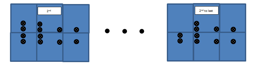
| 1. | Manually measure some across strip ties using the typical layout tools. Search for overlap between strips can be very slow, and occasionally unreliable. Hence having a few manual ties really speeds things up. The recommended practice is to add three points in the corners of the sidelap to the second and second to last image in each strip. These three points should each be measured in at least two images in the other strip. As shown in the picture. This is more data than strictly necessary, but it is also enough to link the strips even if AutoTie across them fails. If the second or second to last image is heavily forested, has a lot of water, etc. then the across strip links should be moved to the nearest image with more conducive features. If the entire strip is difficult it may be best to leave out the ties and do them manually latter. |
| 2. | Back up you ATM files (optional, but recommended) |
| 3. | Semi-Automatic AutoTie (SemTie): This command will link along the strips and attempt to grow links out ward from the manual across strip ties. It does not attempt to fill in the whole block but rather sticks to close around the manual links (this avoids perpetuating any errors). For this reason some users choose to add a few additional cross strip links to long strips. The parameters that have the greatest impact on results are |
| · | Max number of points per image: The more points the better. Remember that SemTie is not the final step. Points will be refined and thinned latter, so have ‘too much’ at this point is not an issue. Collecting at least 3 times as much data as is ultimately desired is recommend in this step. |
| · | Interest points per path: Images are divided in approximately square grids and feature extraction, matching, etc. are done grid by grid. This makes things run much faster and gives better results. A first step in this process is to look at each patch and extract the most interesting points. In order to limit processing time the user can put a ceiling on how many points per patch will be kept. However, if this number goes to low the whole process can fail. It is recommend that user stick with 500 pixel patch sizes and 150-600 points per patch. Cooperative images (e.g. suburban, agricultural, or rural with sparse trees) can get away with lower points per patch. Forests and jungles require higher points per patch. |
| 4. | Back up you ATM files (optional, but recommended) |
| 5. | Free net adjustment (FreNet): Build a set of model space EOs using the frenet adjustment. Clean out auto tie blunders as needed. The bundle interactive GUI (BunInt) can be used to build EO’s and clean AutoTies strip by strip or the black box command (FreNet) is available. |
| 6. | Import the model space EOs using the ImpGps command. |
| 7. | Run a Least Squares Match (LsMat) to refine the measurements, thin the data, and push points through all the images. The parameter that has the greatest impact on results is: |
| · | LS Match sigma: The final stage of AutoTie is Least Squares matching. In this process transformations between patches of pixels are calculated and error propagation can be done to estimate the quality of the match. These estimated accuracies are somewhat analogous to the familiar correlation coefficient in that they reflect on the quality of the match. However, they have the advantage of being in useful units (pixels) as opposed to unit-less correlation. In most cases using the default value of 0.2 gives very good results. However, in very difficult blocks (i.e. thick forests, equatorial jungles, tall leafless trees) this parameter is sensitive. Finding the sweet spot between getting to many false positives and have to little data can be tricky, and it is recommended that you run some tests on a small sub block to make sure it is working. The typical symptom of a LS Match sigma that is too high is poor across strip matches. The typical symptom of a LS Match Sigma that is too low is lack of across strip matches. |
| 8. | Clear EOs (CleEos) to get ready to move to control space. |
Clean up
The free net adjustment is a very powerful way to clean out miss-matches, and must be used if there are no EOs available. It is however comparatively slow. So, provided that the EO’s that were available to import and are at least reasonably good, it is sufficient to bundle adjust (BunAdj) and clean auto ties (CleAut) until satisfied. Otherwise use free net (FreNet) and clean auto tie (CleAut). Remember though, it is recommended that you back up the ATM files before starting however because clean auto tie is irreversible.
The File pull-down menu from the VrAirTrig Main Window
Sets operating parameters for the VrAirTrig Program.
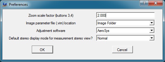
The VrAirTrig Preferences dialog box
Zoom scale factor (buttons 3, 4)
Several orientations, including Relative Orientation, allow zooming in and out on the images. Zoom scale factor sets the scale factor to use while zooming with button 4 (center mouse button).
Image parameter file (.vim) location
Each image used by VrAirTrig has an associated parameter (.vim) file. This file contains the interior orientation values and other image parameters. The image parameter file has the same name as the image but with a .vim file extension. These parameter files may be stored in the same directory as the images ("Image Folder") or they may be stored in the project folder ("Project Folder").
List available adjustment software. Selection VrAdjust makes Ajdustment/AutoTie layout menu active.
Default stereo display mode for measurement stereo view?
Specifies the mode for stereo viewing:
| • | Normal - Uses a stereo compatible screen, emitter, and stereo glasses. |
| • | Anaglyph - Displays in red - blue (or others). This will run on almost any computer and stereo hardware is not required. |
Exits the VrAirTrig program.
Camera
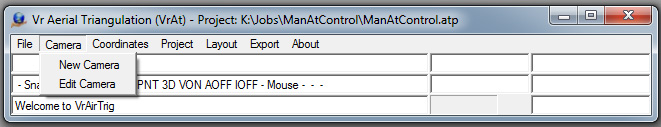
The Camera pull-down menu from the VrAirTrig Main Window
Creates, edits and imports camera calibration parameters.
Creates and edits a new camera calibration file. Prompts the uesr for the file name for the new camera. Camera files in Vr Mapping have a .cam file name extension.
Edits an existing camera calibration file. The camera edited does not need to be one of the current cameras; any existing camera file may be edited. When edit camera starts, the user is prompted for a camera file name. Upon exiting, the has the opportunity to save the modified camera calibration parameters.
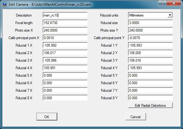
The Edit Camera dialog box
Description
Describes the camera for user reference. This description is for information only and is not used in model orientation.
Fiducial units
Specifies the units of the coordinate positions (millimeters, inches, or pixels). Many programs used to calibrate handheld cameras output the focal length of the camera in pixels. The coordinates entered to represent the fiducial positions must be in the same units as those specified here.
Focal length
Defines the camera lens' focal length, the distance from the focal point to the center of the lens. This value is provided by the camera calibration report. Focal length units should be the same as those used for the fiducial positions.
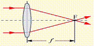
Photo size X Y
Specifies image dimensions. Photo size dimensions should be the same as those used for the fiducial positions.
Calib principal point X Y
Specifies the calibrated principal point (also known as the point of best symmetry). This coordinate position is available from the camera calibration report. Calibrated principal point coordinate units should be the same as those used for the fiducial positions.
Fiducial X Y
The coordinate positions for up to eight fiducials may be entered and must be in the user-specified Fiducial units. Most aerial cameras have eight fiducials. It is strongly recommended that all eight be entered and used to compute interior orientation. If only four fiducials are used, errors may occur and make residuals useless in determining if the wrong camera calibration was selected.
Lens distortion causes image positions to be displaced from their ideal or true locations. In aerial cameras, these distortions are normally minimal but they can still have an effect on accuracy. Some digital cameras have large lens distortions and radial distortions must be entered for accurate mapping results.
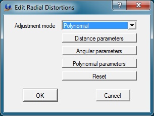
Adjustment mode
Most camera calibration programs output radial distortion values as polynomial parameters. Though angular parameters are listed, this output type is currently unsupported.
Distance Parameters
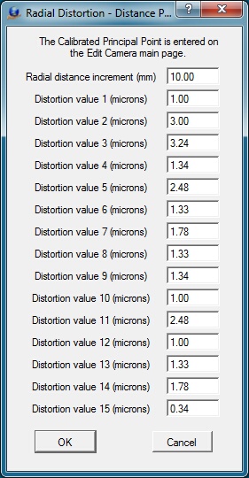
Radial distortions, represented by concentric rings about the camera lens' calibrated principal point, may be entered as distance parameters. The radial distortions shown below are from a small format camera and show high radial distortion values.
Defining radial distortions by distance
Radial distance increment
Represents the distance between the concentric rings that make up the distance parameters. Radial distance increment units should be the same as those used for Fiducial positions.
Distortion value n
Specifies distortion values for each distance. There may be up to 15 values. Distortion value units should be the same as those used for Fiducial positions.
Angular Parameters
Computation of radial distortions by angular parameters is currently unsupported. Please use distance or polynomial parameters.
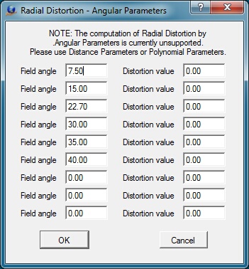
Defining radial distortions by angle
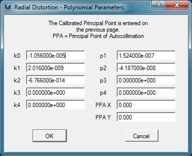
Polynomial Parameters
The polynomial values and principal point or autocollimation are provided by the camera calibration report. The mathematical model used is based on the Simultaneous Multi-camera Analytical Calibration (SMAC) method. Care should be taken when entering these parameters, as entry errors cause model orientation errors and distortions which affect model accuracy.
Entry of Exponential Notation
The k0-k4 values and the p1-p4 values are entered into the Polynomial Parameters dialog box in exponential notation. The values entered from the USGS camera calibration report may have the decimal place moved one position to the left depending on the number entered. For example:
USGS value: 0.1403x10⁻³
Value typed: .1043e-3
Shown value: 1.403000e-004
The Radial Distortions dialog box for entering the polynomial parameters
K0-K4
Defines up to five K coefficient values. These are coefficients of symmetric radial lens distortion from the camera calibration report. These values are entered in exponent form.
P1-P4
Defines to four P coefficient values. These are the coefficients of de-centering distortion from the camera calibration report. These values are entered in exponent form.
PPA X Y
Defines the principal point of autocollimation as provided by the camera calibration report.
Coordinates
The Coordinates pull-down menu from the VrAirTrig Main Window
The Coordinates menu provides functions to create and edit coordinate files. It is possible to import existing coordinate files with a simple name change. Please refer to Vr Mapping Coordinate File Format for information on the format and layout of the coordinate files used in VrTwo.
Creates a new coordinate file. The Format, State Plane Zone, Datum, UTM Zone and Units in the Edit Header dialog box are for user reference only. Prompts the user for a coordinate file name and coordinate file parameters.
The New Coordinate dialog box
Layout
Specifies the fields to be placed in the coordinate file and their order. Options are:
Name X Y Z Cx Cy, Cz
Name Y X Z Cy Cx, Cz
X Y Z Name Cx Cy, Cz
Y X Z Name Cy Cx, Cz
Name X Y Z
Name Y X Z
X Y Z Name
Y X Z Name
X Y Name
Y X Name
Where:
Name – Point name
X Y Z – Coordinates
Cx Cy Cz – X Y Z point weights
Edits coordinates in an existing coordinate file. Editing options include Add, Change, and Delete. When this command is started, the user can open any coordinate (.cor) file and the edited file may be saved upon exiting the application.
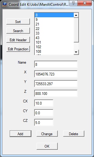
The Edit Coordinates dialog box
Sort
Sorts the coordinate file based on the point name.
Search
Searches for a coordinate point by name. If the point name is found, it becomes the current point.
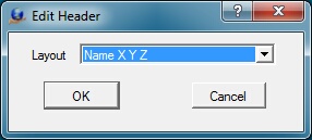
Edit Header
Edits the coordinate file header.
Name
Defines the point name. It must be alphanumeric and may be up to 32 characters in length.
X Y Z
Defines coordinate values for the point.
CX CY CZ
Defines point weights. These may be used in the coordinate file depending on the File Layout. Normally, point weights are expressed in ground units.
Add
Adds the current point to the coordinate file
Change
Updates the current point with the current Name, X, Y, Z, CX, CY and CZ values.
Delete
Deletes the current point.
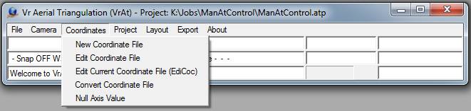
Convert Coordinate File (ConCoo)
Converts an existing coordinate file from its current coordinate projection to a different one. Reads an existing VrOne coordinate file, re-projects it, and writes a new coordinate file. See Coordinate Projections for more information.
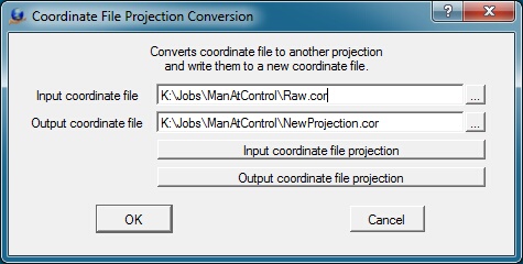
The Coordinate File Project Conversion dialog box
Input coordinate file
Defines the name of the existing coordinate (.cor) file.
Output coordinate file
Defines the name of the output coordinate file.
Input coordinate file projection
Defines or edits the input coordinate file projection. See Coordinate Projections for more information.
The input coordinate projection definition dialog box
Output coordinate file projection
Defines or edits the output coordinate file projection. See Coordinate Projections for more information.
The output coordinate projection definition dialog box
Some points do not have values for all three coordinate axes. The Null Axis Value is an arbitrary figure to which one of a point's 3 coordinate values can be assigned to indicate that it is lacking that value. This value is typically zero, but in cases where zero is a valid coordinate value in the map data, an extreme value like -999 should be used. For example, an elevation-less point could be assigned the coordinates (10, 10, -999) to indicate that it lacks a Z coordinate.
The Null Axis definition dialog box
Project
The Project pull-down menu from the VrAirTrig Main Window
Creates a new project and allows Edit Project to be engaged.
Opens an existing project. It is not necessary to close the current project before opening another. All current project parameters are saved automatically before another is opened.
Edits the current project.
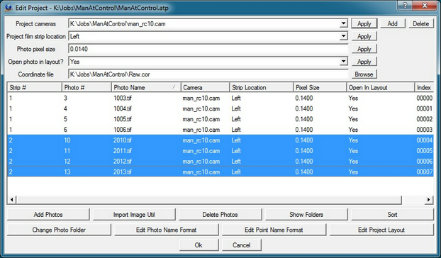
The Edit Project dialog box
Manages project and photo parameters. If there is already a project set up in Image Utility and Interior Orientations have been performed, use the Import ImageUtil option. This reads the list of images from the Image Utility project and automatically recognizes the image settings and interior orientation.
Each image has a camera file, strip location, pixel size, and "open in layout" flag. Use this dialog to assign the correct parameters to all images in the project. A camera file must be added to the project from this dialog before any photos can be added. The photo strip and photo numbers are displayed in the list of photos and are extracted from each photo name. The parameters may be set by pressing the Edit Photo Name Format button.
Placing the mouse pointer on an image and dragging highlights the image in the dialog box. Holding the shift key and clicking the mouse highlights a range of images. Holding the control (Ctrl) key and clicking the mouse highlights additional images. The first four fields ("Project cameras", "Project film strip location", "Photo pixel size" and "Open in layout?") in the Edit Project dialog box are templates which can be copied to a photo or group of photos. To copy these parameters, highlight the photo or photos and press the Apply button on the right side of the of the template field.
Project cameras
Defines up to 10 project cameras (.cam) files.
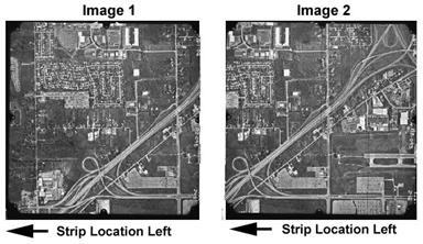
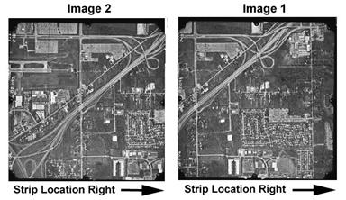
Film strip location
Specifies the film strip location in reference to the rotation of the image. This parameter is not dependent on the direction of flight, but the orientation of the image as viewed by the user. See Film Strip Location for more information.
Photo pixel size
Defines the size of each pixel based on the fiducial coordinate units. Normally expressed in millimeters, but may be in inches or pixels. If the fiducial coordinates are in pixels, the photo pixel size is 1.
Open in layout?
A project in VrAirTrig may consist of thousands of photos. During the measurement process, it is useful to work in one area, so it is not necessary to display all of the project photos in the Layout window. The "Open in layout" flag may be set for a photo or group of photos.
Add photos
Adds photos to the project using the Vr Open file dialog box.
Import Image Util
Imports photo parameters from the Image Utility program into the VrAirTrig project given that the current project was already set up in Image Utility.
Delete Photos
Deletes the highlighted photo or group of photos.
NOTE: Pressing the button deletes without verification.
Show Folders
Toggles display of folder names with the display of each photo name and camera name.
Sort
Sorts the photos by "Strip-Photo Numbers" or "Photo Names".
Change Photo Folder
Changes the location of a photo or group of photos by replacing the file folder name. This operation does not move the photos.
Edit Photo Name Format
Various processes require use of an image strip and photo number. These numbers are typically encoded in the image file name and the Photo Name Format describes the method for extracting this information. See Photo Name Format for more information.
Edit Point Name Format
Determines the format for the point names and the initial poisitions for these points when photo strips are prepared with pass points. See Point Name Format for more information.
Edit Project Layout
During the measurement process, points are transferred from one photo to another as they are propagated to all photos they fall within. For this process, the approximate project photo overlap, sidelap, and strip numbering direction must be known.
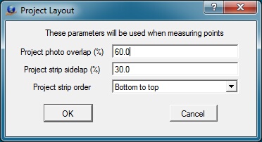
Project Layout dialog box
Project photo overlap (%)
Defines the project photo overlap as a percentage. The typical overlap for aerial phtography is 60%.
Project strip sidelap
Defines the project photo sidelap as a percentage. The typical sidelap for aerial photography is 30%.
Project strip order
Defines project strip numbering order. Options are "Bottom to top", "Top to bottom", and "Strip". "Strip" defines flight lines that are continuous strips without overlap.
Moves the contents of a VrAirTrig project project to another file. This routine does not move any of the files to another folder, but assumes they have already been moved. The Change Drive routine modifies the necessary VrAirTrig parameter files to reflect the move.
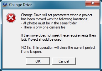
The Change Drive dialog box
There are some limitations on the data that can be moved to another folder:
| • | All photos must be in the same folder; |
| • | There can only be one camera file. |
If there is more than one camera file, the camera files must first be reassigned in Edit Project.
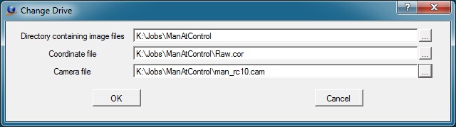
The Change Drive dialog box showing the new location for the project files
Directory containing image files
Defines the directory that contains all project images.
Coordinate file
Defines the new location of the coordinate (.cor) file.
Camera file
Defines the new location of the camera (.cam) file.
SS Import Wizard (SsImp)
Creates a VrAt project from Socket Set import files.
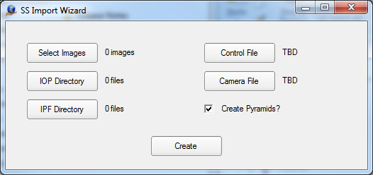
The camera file must have been created previously, and TIFs, IOPs, and IPFs must reside in a single directories.
This function is currently not active.
Export
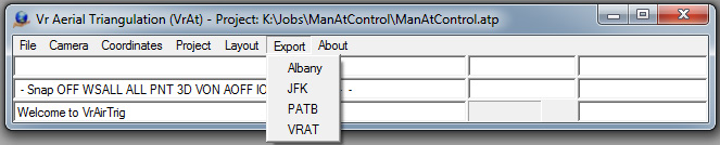
The Export pull-down menu from the VrAirTrig Main Window
Measurements made in VrAirTrig can be exported in several formats, including Albany, JFK, PATB, and VRAT (VrAirTrig). Other aerial triangulation programs can use these measurements to perform the bundle adjustment. The measurements can also be used by the VrTwo Orientation program for model setups.
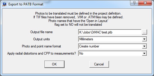
The Export dialog for output in PATB format
Output file name
Defines the output file name for the measurements.
Output units
Specifies units for the output file (Millimeters or Microns).
Photo and point name format
Determines the output name format. The exported photo and point names may be output in numberic ("Create number") or alphanumeric ("Create name") characters . "Create number" removes any non-numeric characters from the photo and point names during output. "Create name leaves photo and point names unchanged.
Apply radial distortions and PPA to measurements?
Specifies whether radial distortions and principal point offsets should be applied to the measurement output. "No" should be selected if the target triangulation program, to which the file is being exported, will apply these values.
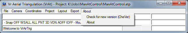
The About pull-down menu from the VrAirTrig Main Window
Check For New Version (CheVer)
Checks the Cardinal Systems web page for a more current version of the software.
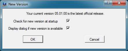
The Check for a New Version dialog box
Check for new version at startup
Specifies whether to check for a new version on program startup.
Display dialog if new version is available
Specifies whether to display a dialog box if a new version is available.
Displays the current software version and the software solution platform (32 or 64-bit) for the currently running version.
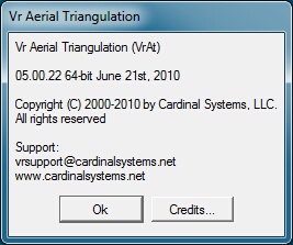
The About dialog box
Credits
Displays the copyrights of the third party software used by Vr Mapping.
Layout Applications
Three measurement environments are available:
| • | Model mode (Measure) – Displays two images in a model format. A least-squares best fit is computed once at least six points have been measured. This helps avoid point identification errors. If a point has more than one ray, the point is held on one image. The corresponding image is then adjusted to the held image. Remeasure can be started from Measure. This is useful when a point is not visible from a new strip and must be moved on all images. |
| • | Remeasure mode (Remeasure Point) – Displays image patches of all images which contain the point. A point may be remeasured using one of the three measurement methods: mono-comparator mode, correlate mode, or measure in stereo. |
| • | Stereo (Stereo Measurement) - The current point may be measured in stereo. |
Measures points on photos in a Relative Orientation format. Two photos are used at a time. This method measures pass, tie, and control points between overlapping and sidelapping photos. It starts from the Layout environment.
There are three point measurement methods. Any of the three methods can be used at each point. Ground features change from point to point; one point may be on a city street and the next in trees. No one measurement technique will suit every point. The three measurement methods are:
| • | Mono-comparator - A common point is selected in the left photo. The same point is selected in the right photo."Measure" (button 1) is used to measure the point on the left and right photos. The left mouse button should be used to make the measurements. |
| • | Semi-automatic correlation assist - The cursor is positioned (do not press any buttons) in one of the measurement windows. Then, "Correlate" (use F7 to avoid moving the cursor) is engaged to find the corresponding location in the other photo. The correlation will display the matching point in the other measurement window. The cursor may be placed in the left or right measurement window. After correlation, the results are displayed in the At Measure dialog box and in the Menu Keys dialog box. A result of 0.9 to 1.0 is good, 0.8 to 0.9 acceptable, 0.7 to 0.8 poor, and anything less than 0.7 unacceptable (correlation should be rejected). |
| • | Stereo - Photos are displayed in stereo. The parallax is cleared at the point location. This operation is similar to the method used on analytical stereo-plotters. Features include image correlation, dove prism adjustment (rotation of one photo), and photo scale factor adjustment (changing the scale of one photo). Both photos can be rotated 0, 90, 180 and 270 degrees to better display stereo for point measurement between strips. Pressing "Stereo" (button 6) starts stereo measurement. |
Before Measure starts, two photos must be identified. These photos must be overlapping and/or sidelapping.

The VrAirTrig Measurement environment
Measure launches several windows:
1. Menu Keys Dialog Box - Displays the active menu and the functions associated with it. Buttons in this window may be pressed with the mouse or engaged with their associated function keys (F1-F12). During measurement, several of these buttons are mapped onto the mouse. and in these cases the mouse buttons should be used instead of pressing the buttons in the dialog box. When a button has been mapped to the mouse, the necessary click is indicated with "Left", "Right", or "Center". This allows actions to be taken without moving the cursor during measurement.
2. At Measure Dialog Box - Displays point names, left and right coordinates, model coordinates and residuals for each point, along with the current Total RMS Error. Displays unmeasured points in red. Displays measured points in blue.
3. Overview Windows - Display the entire left and right photos.
4. Measurement Windows - Used for measurements. Measurements are made by placing the cursor in one of the windows and performing one of the three measurement methods.
Each measurement window's top border contains the photo name and the measurement status ("MEASURE" or "HOLD") of that side's point.
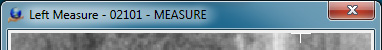
Measurement window indicating the point may be measured
If the status is MEASURE, a point can be measured in that side.
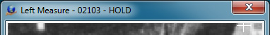
Measurement window indicating the point is held and cannot be measured
If a point in the left or right side has already been measured in two or more other photos (two or more rays), it is flagged "HOLD". A held point may not be measured unless it is released by pressing "Release Side" (button 8). This is a safety feature, ensuring that points that have been measured in two or more photos are not moved when a new photo is observed. To release a side, press F8 while keeping the cursor in the target measurement window. If one side is flagged as HOLD and the other side is flagged as MEASURE, the point in the MEASURE side may be measured to match the point in the HOLD side.
If one side is held and the other side can be measured, the cursor can be in either measurement window when correlation is used. It does not need to be on the point when the "Correlate" button is pressed. The measure side will be correlated to the held side.
To change a point location in all photos, use "Remeasure point" (button 9).
The following are the functions available in "Measure":
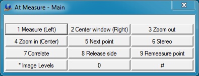
The VrAirTrig Layout Measure Main Menu Keys
1 Measure (Left)
Measures points. Press button 1 in one of the measurement windows to measure a point. The same point is measured in the other window.When in one of the Overview windows, the cross cursor will change to a square. Clicking the left mouse button centers the measurement window to the area under the cursor.
2 Center window (Right)
Centers the current window at the current cursor location.
3 Zoom out
Zooms the current window out x2. If the cursor is in one of the Measurement windows, both Measurement windows are zoomed out.
4 Zoom in (Center)
Zooms the current window in x2. If the cursor is in one of the Measurement windows, both Measurement windows are zoomed in.
5 Next point
Moves to the next point.
6 Stereo
Changes from the left and right measurement method to a stereo method. The two Measurement windows are replaced by a single stereo window for measurement of the current point. See Stereo Measurement for more information.
7 Correlate
The cursor is positioned (do not press any buttons) in one of the measurement windows. Then, "Correlate" (use F7 to avoid moving the cursor) is engaged to find the corresponding location in the other photo. The correlation will display the matching point in the other measurement window. The cursor may be placed in the left or right measurement window. After correlation, the results are displayed in the At Measure dialog box and in the Menu Keys dialog box. A result of 0.9 to 1.0 is good, 0.8 to 0.9 acceptable, 0.7 to 0.8 poor, and anything less than 0.7 unacceptable (correlation should be rejected).
8 Release side
Releases the side in which the cursor is currently positioned. This side can now be remeasured. Useful if a side is being held because it has been measured in two or more photos
9 Remeasure point
Displays image patches of all images which contain the point. A point may be remeasured using one of the three measurement methods.
* Image Levels
Makes level adjustments to opened images. Input, output, and gamma settings can be altered. Level adjustment settings can be saved with each image so that it they are automatically loaded when the image opens.
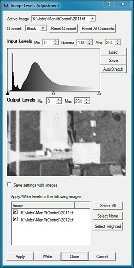
The Image Levels Adjustment dialog box
Press "Ok" in the At Measure window to exit Measure and return to the previous Layout menu.
Displays image patches of all images which contain the point. A point may be remeasured using one of the three measurement methods: mono-comparator mode, correlate mode, or measure in stereo. Point hold flags are ignored; any point can be changed.
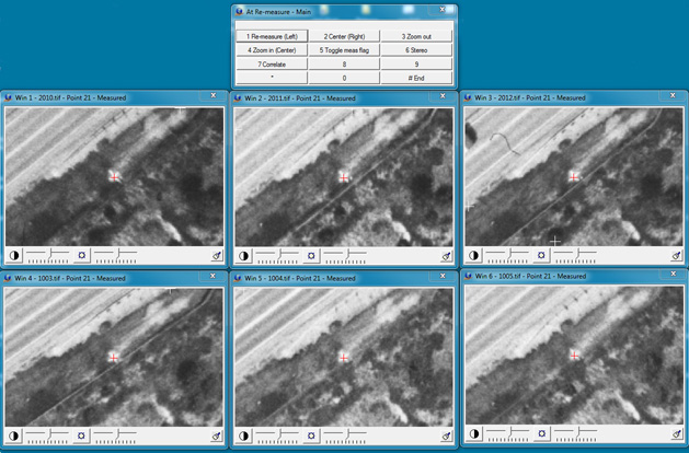
The VrAirTrig Remeasure Point environment
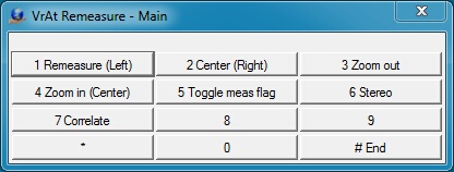
The VrAt Remeasure Point Menu Keys
1 Remeasure (Left)
Remeasures the point at the current cursor location in the image patch.
2 Center (Right)
Centers the current image patch at the cursor location.
3 Zoom out
Zooms out all image patch displays x2.
4 Zoom in (Center)
Zooms in all image patch displays x2.
5 Toggle meas flag
Allows an image patch to be identified for its flag to be toggled between measured and unmeasured. Useful when Remeasure is started using a point that has not yet been measured, as is the case when Drive Point is used in Layout.
6 Stereo
Allows to image patches to be identified and starts the Stereo Measurement application. See Stereo Measurement for more information.
7 Correlate
Allows a source image patch to be identified and target image patches to be correlated to the base patch.
# End
Exits Remeasure Point and returns to the previous menu.
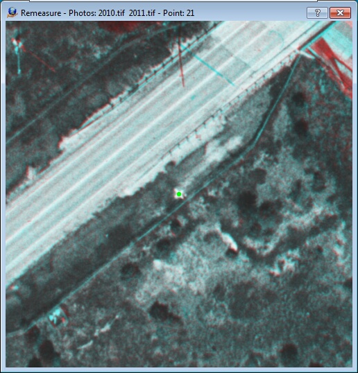
The VrAirTrig Stereo Measurement window (Anaglyph)
During the Measure and Remeasure Point applications, a point can be measured in stereo. Once the point is measured, the program returns to the previous environment.
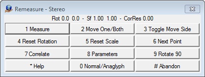
The VrAirTrig Stereo Measure Menu Keys
1 Measure
Measures the point in stereo and records the position on both images.
2 Move One/Both
Toggles the movement of the images from both moving to one moving. When the mode is set to one image moving, parallax can be cleared at that location.
3 Toggle Move Side
Toggles the image side to move between left and right when clearing parallax.
4 Reset Rotation
Resets the current image rotation. See Rotating One Image.
5 Reset Scale
Resets the current image scale to 1.0. See Scaling One Image.
6 Next Point
Advances to the next point
7 Correlate
Correlates the two images with a common point.
8 Parameters
Sets stereo parameters.
9 Rotate 90
Rotates both images 90 degrees. Useful when viewing stereo between strips, as sidelap does not produce viewable stereo in this situation.
* Help
Displays help.
0 Normal/Anaglyph
Toggles between standard and anaglyph stereo display modes.
# Abandon
Quits stereo mode and returns to the previous environment without making a measurement.
Additional Features and Controls When in Stereo Mode
| • | Changing the Cursor Color – Roll the mouse wheel to change between cursor colors of green, red, black, white, yellow or blue. |
| • | Changing the Cursor Size – Press and hold the Alt on the system keyboard and roll the mouse wheel. |
| • | Zoom Up – Also known as Zoom Out. Press Page Up on the system keyboard |
| • | Zoom Down – Also known as Zoom In. Press Page Down on the system keyboard. |
| • | Center Images – Press the Home key on the system keyboard to center both images at the current cursor location. |
| • | Load More Image – Two image patches are used to display stereo. If the cursor moves large X and/or Y distances, the edges of the current image patches can be reached. Press the Home key to load more image data around the current cursor location. |
| • | Disengage Cursor – It may be necessary to disengage the stereo cursor in order to perform an operation with the system mouse pointer like resizing a window. Press the Insert key to disengage the stereo cursor. Press the Insert key again to re-engage the stereo cursor. |
Reference
Vr Mapping Coordinate File Format
The Vr Mapping coordinate file (.cor) comprises a header and a list of point names, coordinates, and optional weights. Fields may be arranged in several different orders. The file is an ASCII file and may be viewed with any text editor. Documentation about the file format is included in each file header. The following is a typical Vr Mapping coordinate file.
# Coordinate File
# Layout - Field Order Min number of fields
# 0 NAME X Y Z CX CY CZ 3
# 1 NAME Y X Z CY CX CZ 3
# 2 X Y Z NAME CX CY CZ 4
# 3 Y X Z NAME CY CX CZ 4
# 4 NAME X Y Z 3
# 5 NAME Y X Z 3
# 6 X Y Z NAME 4
# 7 Y X Z NAME 4
# 8 X Y NAME 3
# 9 Y X NAME 3
#
# Format - Coordinate format
# 0 State plane
# 1 UTM
# 2 Geographic Decimal Degrees
#
# SpZone - State plane zone
#
# Datum - Datum
# 0 NAD1927
# 1 NAD1983
#
# UtmZone - UTM Zone
# 1-60 UTM zone number
#
# Units - Coordinate units
# 0 Us Foot
# 1 International Foot
# 2 Meters
# 3 Inches
# 4 Pixels
#
Layout 4
Format 0
SpZone 901
Datum 0
UtmZone 17
Units 0
#
201 837831.194130 951352.037020 303.8200
202 836399.079330 951266.642540 337.6800
203 837994.618340 950634.951710 299.6000
204 836711.670600 950565.198920 326.3200
205 836018.411470 950724.804370 309.2900
Any record starting with a # symbol is considered a comment. The Layout is the most important keyword in the file as it specifies the order of the fields.
Importing a File to Use as a Vr Mapping Coordinate (.cor) File
Any ASCII file in the following format may be read by Vr Mapping. The file must have a .cor file name extension and the fields must be separated by one or more blanks or tabs. Following is an example of an ASCII file that would be acceptable to reading by Vr Mapping. This file consists of a point name followed by X Y and Z.
35 1410993.867000 667652.883000 268.0300
36 1421351.907000 670064.772000 251.8240
37 1432756.960000 660002.435000 438.6740
38 1426080.595000 651648.623000 417.5070
39 1437426.118000 648649.673000 256.5350
99999 1440539.957000 647417.838000 241.1880
2727011 1410534.575000 658885.235000 294.5090
2727012 1412335.275000 659061.598000 280.9620
2727021 1410279.378000 661225.872000 260.6650
2727022 1412458.095000 661055.148000 284.6200
2727023 1413884.366000 661259.361000 425.0660
2727031 1410433.453000 663554.024000 267.3830
2727032 1412556.566000 663154.921000 244.1890
2727033 1414464.428000 663015.598000 460.9970
Location of the cameras data strip in reference to the rotation of the image. This parameter is not dependent on the direction of flight, but rather the orientation of the image as seen by the user. The following is an example of strip locations.
The data strip is to the left.
This is the same model as above, but with the images rotated 180 degrees. The strip location is now to the right.
Various processes, such as aerial triangulation and model orientation, require use of an image strip and photo number. These numbers are typically encoded in the image file name and the Photo Name Format describes the method for extracting this information.
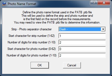
The parameters describe the Photo Name Format. If the separator character is used to describe the format, the remainder of the parameters are not needed and can be ignored. If the file name does not have a separator character, the start character and number of characters must be used.
The photo separator character may be Underbar ‘_’, Dash ‘-‘, or Tilde (~). Following are several examples of the Photo Name Format:
Photo name: 23-56.tif
Photo separator character: Dash
Start character for strip number: any
Number of digits for strip number: any
Start character for photo number: any
Number of digits for photo number: any
Strip number: 23
Photo number: 56
Photo file name: 23056.tif
Photo separator character: None
Start character for strip number: 1
Number of digits for strip number: 2
Start character for photo number: 3
Number of digits for photo number: 3
Strip number: 23
Photo number: 56
Photo file name: 23056.tif
Photo separator character: None
Start character for strip number: 1
Number of digits for strip number: 3
Start character for photo number: 4
Number of digits for photo number: 2
Strip number: 230
Photo number 56
When photo strips are prepared with pass points, the Point Name Format determines the format for the point names and the initial position for these points. The number of pass points per photo can be set (maximum 9).
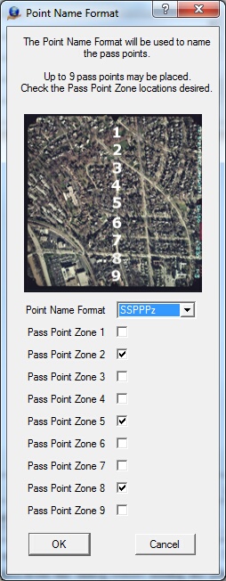
The Point Name Format dialog box
Point Name Format
Defines the format for the point names when preparing a strip of photos. The following are the options for this format and examples of each:
Format |
Example: Strip Number:2 Photo Number:5 Zone:3 |
S_Pz |
2_53 |
S-Pz |
2-53 |
SPz |
253 |
SPPz |
2053 |
SSPPz |
02053 |
SPPPz |
20053 |
SSPPPz |
020053 |
SSSPPPz |
0020053 |
Pass Point Zone
Up to nine pass points may be placed on each photo. The locations of these points are called zones and the number of pass points and the zone locations may be selected by using the check boxes next to each zone.
Auto Tie FAQs / Custom Workflows
How do we densify a block of measurements? Some users want to use AutoTie only after they have minimally tied a block of images manually. The Auto Densify (AutDen) was written for them. It does not look for any new overlaps, but adds more data to those that are already known. That is if imageA and imageB already have some ties between them then it will attempt to add more. If EO’s have been imported (see ImpGps) this process will also extend matches into new images.
What is the best way to thin data? Least Squares match (LsMat). The LsMat command can be used to thin data, refine data, and push measurements through to more images (if EO’s have been imported).
How do we deal with EO’s in one coordinate system and control in another? Auto Tie is designed to work in any rectangular coordinate system. So the approach taken is to do the auto tie in one system and then switch to the other.
| 1. | Use the EO’s to help generate the auto ties normally. |
| 2. | Bundle adjust and clean the auto ties normally as well. |
| 3. | Then clear the EO’s (see CleEos) so that there won’t be used in the bundle adjustment. |
| 4. | Measure at least three ground control points |
| 5. | Run the black box bundle adjustment command, BunAdj. |
| 6. | Use drive control (from the layout points menu) to measure the rest of the control |
What is the fastest/best way to run a strip job? This answer depends, but the short version is: Just like any other block. If you have EO’s then use the work flow given EO’s. If you don’t you must follow the workflow without EO’s, which requires the user to provide some ties between the strips.
In the special case of single strip job the SemTie work flow is frequently the fastest whether you have EOs or not. This is counterintuitive, but to run SemTie does not require EO’s to be imported or even a correct camera file. Further on a single strip no manual measures are required. Hence, as soon as strip and photo numbers can be assigned it can run—users can worry about importing EO’s, setting up cameras, etc. later if at all. Users with small jobs really appreciate this simplicity.
Can blocks be run in sections? Yes, the Auto Tie Parameter ‘Min Auto Tie Sequence number’ allows user to start auto tie numbering arbitrarily and avoid duplicate point names in sub-blocks. For example: In a 30 strip job, strips 1-11 could be run with a ‘Min Auto Tie Sequence number’ of 0, strips 11-21 with a ‘Min Auto Tie Sequence number’ of 1000000, and strips 21-30 with a ‘Min Auto Tie Sequence number’ of 2000000 (If there might be more than a million auto ties in a sub-block use additional zeros). Care must be taken that the ATM files of the separate runs do not overwrite each other. The surest way to do this is to set up different projects (IN DIFFERENT DIRECTORIES) that reference the sub sets of images, but it can also be accomplished with the BacAtm command. The ATM files can then even be combined for a final bundle.
How do we get more multi-ray (cross-strip) points? The best way to do this is to get lots of along strip matches and good EO’s then use LsMat to push the along strip matches through to the other images. The best way to go about doing it depends on what data is already available. For instance:
| • | If there are no EO’s then the SemTie (no EO) workflow can be followed to get along strip matches and EO’s. |
| • | If EO’s are available, but not reliable, FasTie or AutoTie may not work (this usually only happens if EO’s are grossly in error). In this case it is possible to fall back to the SemTie workflow or simply put in enough manual points to get the EO’s reasonable, bundle, import the ExtOri report as new GPS values, and return to following the EO workflow. |
| • | If EO’s are good, but points are sparse it may be sufficient to run a densification (AutDen) |
| • | If EO’s are good and points are sufficient dense simply run LsMat. |
In all of these examples the LS match max axial sigma parameter needs to be set well. If it is too small it there will be too few matches. A range of (0.05-0.25) usually works well.
How do we know if the points are good? Statistics and residuals are great tools (as in bundle residual reports), but in addition I highly recommend that users look at a sample of the points. Choose cross strip points scattered around the project to get a feel for their quality. In particular watch for systematic errors (features match within strips but not across them). Running a free net is also a good idea. It can be slow, but it will also reveal any problems in the block more reliably than a bundle. A few strategically added manual points can also help gauge the quality of a block—if the bundle wants to flag the manual points as blunders there may be an issue with the auto ties. In short, be conscientious, particularly in forests and jungles. If a block would be hard for a human it will be hard for a computer.