Vr Mapping |
ON-LINE REFERENCE DOCUMENTATION CARDINAL SYSTEMS, LLC |
Vr Aerial Triangulation Tutorial
A tutorial for the Vr Aerial Triangulation Program (VrAt) (VrAirTrig)
See also: Vr Air Trig - Documentation
Section 3 Adding Control Points
Section 7 Exporting Measurements
The Vr Aerial Triangulation program (VrAirTrig) allows the collection of strip and tie points on a large number of photos and performs a block adjustment using aerial triangulation methods. The optional AeroSys adjustment software is integrated directly with VrAirTrig to perform seamless adjustments. Several third party adjustment packages may also be used by using an export and import method.
VrAirTrig provides a Layout window that enables the technician to layout project photos as if on a desktop and to display point readings as either "to be read" or "completed". The Layout tool shows the completion status of the project and allows operations such as the addition of control points and various other tools.
VrAirTrig's intuitive interface allows setting up, reading, and exporting aerial triangulation readings on up to 2000 photos.
Points may be measured in one of three methods with include Mono-comparator, Semi-automatic correlation assist, and Stereo. Each method is described in more detail in the Using VrAirTrig section.
Before starting a VrAirTrig project, raw photos, a ground control file, and a camera calibration report are required.
Requirements for Project setup
| 1. | Camera File - The camera file may be imported or generated from a camera calibration report. |
| 2. | Ground Control File - The ground control file contains points that were obtained from sources such as ground surveys. |
| 3. | Photos - Raw photos that have not been edited or modified. |
| 4. | Correct Photo Overlap - The photo overlap must be on inside of photos or in ortho mode. This may require that the photos be rotated. This photo rotation should be done before Interior Orientations are done. If photo rotation is required, this task can be performed, in batch, in the Vr Image Utility program. |
| 5. | Interior Orientations - This can be done manually in VrAirTrig or be done in the Vr Image Utility program |
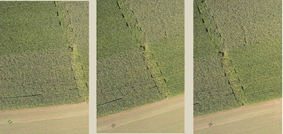
An example of photo overlap to the inside (ortho)
Creating or Editing the Camera File
Click on Camera then New Camera or Edit Camera.
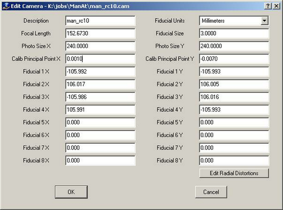
The Edit Camera dialog box used to define a camera calibration
Creating or Editing a Control File
Create a new coordinate file if one does not exist. Click on Coordinates then New Coordinate File.
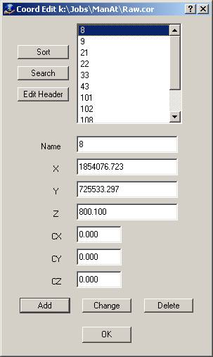
The Coordinate Edit dialog box for entering or editing control points.
If a control file exists and contains the PointName X Y Z fields, it can be used directly by the various programs in Vr Mapping, including VrAirTrig. Simply rename the file by replacing the file postfix with .cor. For example, if a coordinate file is named TheCoords.txt and contains the PointName X Y Z fields, then it can be renamed TheCoords.cor and be subsequently used by VrAirTrig.
The following is an example of a contents of a coordinate file compatible with Vr Mapping:
201 837831.194130 951352.037020 303.8200
202 836399.079330 951266.642540 337.6800
203 837994.618340 950634.951710 299.6000
204 836711.670600 950565.198920 326.3200
205 836018.411470 950724.804370 309.2900
The first field is the point name followed by the X, Y and Z coordinates.
Creating or Editing a Project
Create a new project file by clicking on Project ,then New Project, then Project Edit Project
| 1. | Add Project Camera(s) |
| 2. | Set strip direction |
| 3. | Set Pixel Size. |
| 4. | Add Coordinate file |
| 5. | Click on Add Photos at the bottom of the screen to add all raw photos. |
| 6. | Click on Edit Project Layout Standard settings are shown (Photo Overlap 60% Sidelap 30%) |
| 7. | Press OK, Then Press OK again at the bottom of Edit Project |
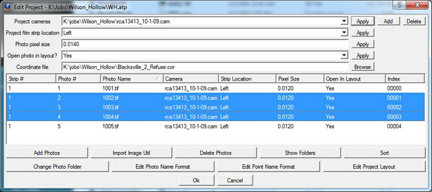
The Edit Project dialog box for VrAirTrig
The Edit Project dialog box is designed to allow the definition of multiple photo files. Each photo file has a Photo Name Format which are parameters that define the strip and photo number from a photo file name. Also defined for each photo is the Strip Direction, Pixel size and the Open In Layout flag. The top portion of the dialog box is a template of these parameters that may be copied to a photo or group of photos by selecting a photo or dragging the cursor over a group of photos then pressing the Apply button for that item.
Opening the Layout Window
The Layout window is the work flow focal point for aerial triangulation collection, measurement progress, and point management, along with other features. It is similar to using a table top to lay out the photos for an aerial triangulation project. There, photos could be prepared by directly placing pass, tie, and control points on them. VrAirTrig modernizes this concept with more features and functions.
If this is the first time that Layout is used for this project, the photos will need to have their initial positions computed for the Layout window. Choose Layout -> Set Photo Positions from the pull-down menu to perform this operation. For the Layout window, it is typical to use zero for the over-lap and side-lap parameters.
Open the Layout tool by choosing Layout -> Open Layout from the pull-down menu.
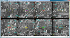
The VrAirTrig Layout window
When the Layout window is open for the first time in a project, the window may appear with a black background with no photos displayed. Press the Zoom All button in the lower left corner of the Layout window to display all the photos.
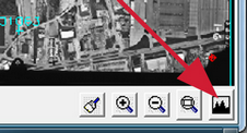
The Zoom All button in the Layout window
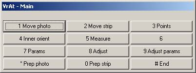
Above the Layout window should be the VrAirTrig Menu Keys dialog box. This dialog box controls many of the VrAirTrig operations.
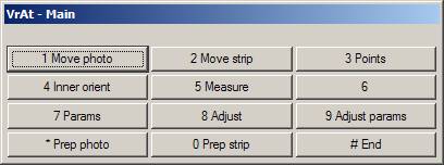
The VrAirTrig Layout window Main Menu Keys dialog box
The VrAirTrig Layout window is the focus point for the job work-flow and once the Layout window is open various operations may be performed including point management, starting measurement and re measurement operations, block adjustment, blunder detection, and final aerial triangulation adjustments.
Preparing Strips for Pass Points
| 1. | Press the "Prep strip" button (button 0) |
The VrAirTrig Layout window Main Menu Keys dialog box
| 2. | Press the "Pass points" button (button 1) |
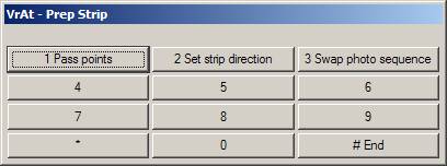
The VrAirTrig Layout window Prepare Strip Menu Keys dialog box
| 4. | NOTE: If there are existing measurements on the strip being prepared, these measurements will be overwritten. If this is acceptable, press OK. |
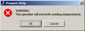
A warning that data will be overwritten
| 6. | Press "Id strip" (button 1). |
| 7. | Identify each strip to which to add "Pass points" by clicking on the strip of photos in the Layout window. |
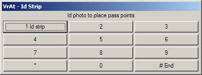
The VrAirTrig Layout window Identify Strip Menu Keys dialog box
Below is shown two photos after the "Prep strip" operation. The unmeasured pass points are shown in red.
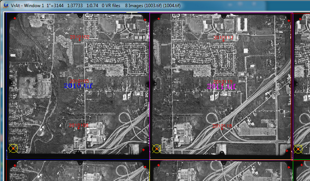
A potion of the Layout window showing the results of the Prepare Strip operation
Section 3 Adding Control Points
Adding Control Points to the Project
The following process allows the addition of ground control points to the current project.
| 1. | Press the "Points" button (button 3) |
The VrAirTrig Layout window Main Menu Keys dialog box
| 2. | Press the "Add points" button (button 1) |
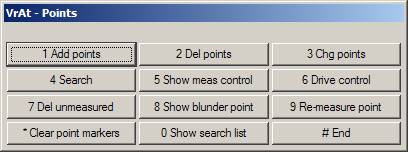
The VrAirTrig Layout window Points Menu Keys dialog box
| 3. | Press "Id point" (button 1) and select the control point location on one of the photos in the Layout window. The control point may be placed in its approximate location and it needs to be placed only on one photo. During the measurement process, the control point will be placed at its proper location and will propagate its position to all overlapping photos. |
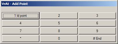
The VrAirTrig Layout window Add Point Menu Keys dialog box
| 4. | Enter the "New point name". This name must match a point name in the ground control (.cor) file for it to be considered in the block adjustment as a ground control point. |
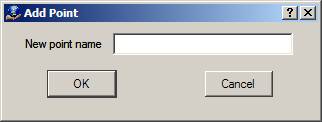
Add point dialog box
| 5. | Repeat this process to place other control points. If VrAdjust (AeroSys) is being used, it is not necessary to place all the control points at this time. A lesser quantity of control points may be placed now. After a block adjustment has been performed, the Drive Control function may to used to drive to unmeasured control points for measurement. |
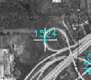
A potion of the Layout window showing the addition of a control point
Measuring Control, Pass, and Tie Points
There are three methods to measure points. All three methods are available at each point. Because the ground features change from point to point, where one point may be on a city street and the next may be in trees, one method of measurement will not suit all situations. The three measurement methods are:
| • | Mono-comparator - A common point is selected in the left photo and the same point is selected on the right photo. The "Measure" (button 1) is used to measure the point on the left and right photos and the left mouse button should be used to make the measurements. |
| • | Semi-automatic correlation assist - The cursor is positioned on one photo and its corresponding location is found on the other photo by pressing the "Correlate" button (button 7). It is recommended that the system keyboard button F7 is used for this operation. When using correlation assist the cursor is positioned (do not press any buttons) in one of the measurement windows and then the "Correlate" (button 7) is pressed to find the corresponding point in the other photo. The correlation will display the matching point in the other measurement window. The cursor may be placed in the left or right measurement window. After correlation, the results are displayed in the At Measure dialog box and in the Menu Keys dialog box. A result of 0.9 to 1.0 is good, 0.8 to 0.9 is acceptable, 0.7 to 0.8 is poor and the correlation should be rejected with results less than 0.7. |
| • | Stereo - Photos are displayed in stereo and parallax is cleared at the point location. This operation is similar to the method used on analytical stereo-plotters. Options in this mode include image correlation, dove prism adjustment (rotation of one photo) and photo scale factor adjustment (changing the scale of one photo). There is also an option to rotate both photos 0, 90, 180 and 270 degrees to better display stereo for point measurement between strips. The stereo mode of measurement may be started by pressing the "Stereo" (button 6). |
The VrAirTrig Layout window Main Menu Keys dialog box
There are two environments for measuring points. Both measurement methods are used measure or remeasure pass points, tie points and ground control points. The two measurement environments are:
| • | Measure mode – Two photos are displayed in a Relative Orientation format. A least squares best fit is computed when at least six points have been measured. This method helps identify blunders between conjugate points in two photos. If a point has more than one ray then it is held on one photo and the corresponding photo must be adjusted to the held photo. It is possible to start the remeasure method described below from the Model mode of measurement and return. This is useful when a point is not visible from a new strip and must be moved on all photos. |
| • | Remeasure mode – Photo patches of all photos that contain the point are displayed on the screen. A point may be remeasured using one of the three measurement methods. |
Making Measurements in Measure Mode
Press the "Measure" (button 5) button then identify the first two photos.
The VrAirTrig Layout window Main Menu Keys dialog box
Move the cursor over a photo in the Layout window and press the "Id photo" (button 1) button. Repeat this for the second photo. The two photos to be measured may overlap on the same strip or may side-lap between strips.
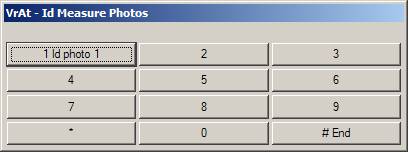
The VrAirTrig Layout window Identify Measure Points Menu Keys dialog box
Once the two photos to be measured have been identified, the measurement windows and dialog boxes are displayed.
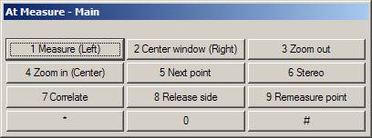
Menu Keys Dialog Box
The Menu Keys dialog box displays the active menu and the functions that are associated with it. Buttons in this window may be pressed by placing the mouse over them or with the associated F1-F12 keys on the system keyboard. During measurement, several of these buttons are mapped onto the mouse and in these cases the mouse buttons should be used instead of pressing the buttons in the dialog box. When a button has been mapped onto the mouse a notation of (Left), (Right) or (Center) indicating the left, right and center mouse buttons. When measuring, the mouse pointer becomes the measuring device, so pressing buttons on the mouse instead of the dialog box is necessary.
At Measure Dialog Box
This is the dialog box in the upper right corner of the screen. The point names, left and right coordinates, model coordinates and residuals are displayed for each point along with the current Total RMS Error. Points that are displayed in red are unmeasured while points displayed in blue are measured.
Overview Windows
These windows are the two windows on the left and right edges of the screen that display the entire left and right photos.
Measurement Windows
The two middle windows are used for measurements.and measurements are made my placing the cursor in one of the windows and performing one of three measurement methods.
Each measurement window's top border contains the photo name and the measurement status of the point for that side. The measurement status can be MEASURE or HOLD.
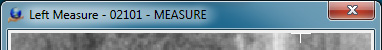
Measurement window indicating the point may be measured
If the status is MEASURE, then the point may be measured in that photo.
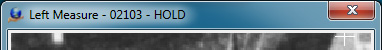
Measurement window indicating the point is held and cannot be measured
If a point in the left or right side has already been measured in two or more other photos (two or more rays), it will be flagged has HOLD. If the point is being held it may not be measured unless it is released by pressing "Release Side" (button 8) . This is a safety feature to ensure that common points that have been measured on two or more photos are not moved when observing a new photo. To release a side, the system keyboard button F8 must be pressed while the cursor remains in the target measurement window. If one side, left or right, is flagged as HOLD and the other side is flagged as MEASURE, the point in the MEASURE side may be measured to match the point in the HOLD side.
If the location of a point needs to be moved in all the photos, the "Remeasure point" (button 9) function can be used.
The VrAirTrig point measurement environment (similar to Relative Orientation)
A Measurement Work-flow
The suggested work-flow for measuring points is to first tie the photos together on a single strip and then tie that strip to the strip above and/or below it. The process is then repeated for the other strips.
The necessity of tying one strip to another and then "cross tying" points back to the first strip after the second strip has been measured is determined by the measurement philosophy of the company. It is suggested that "cross tying" is not needed.
Running a Block Adjustment
Running the block adjustment from inside VrAirTrig is possible if the current configuration is using the optional VrAdjust (AeroSys) package. There are two adjustment modes when using VrAdjust from VrAirTrig. The first is “Check Photogrammetry”, which forms photos into strips and forms the strips into a block.This step checks the Photogrammetry and yields results based on the accuracy and tie quality of the points without consideration of the ground control file (though enough ground control points must be measured to allow the adjustment to solve). The second mode is “Full”, where photos are formed into strips and the strips are formed into a block and fit to the ground using the ground control file.
Each of the adjustment modes reports results as residuals. The results from “Check Photogrammetry” are expressed as a statistical number and the results from the “Full” adjustment are expressed in ground unit residuals. It is possible to change point weights to allow suspect points to “float”. If a point has been floated and the adjustment has been run at least once, use "Drive Control" to drive to the point's computed position. This is useful if there are misidentified control points.
After an initial block adjustment, it is possible to drive the layout window the blunder points. It is also possible to drive to unmeasured control points and mark a control point position for remeasure and inclusion in the next block adjustment.
To display the adjustment parameters dialog box, press "Adjust Params" (button 9) from the Main menu in Layout.
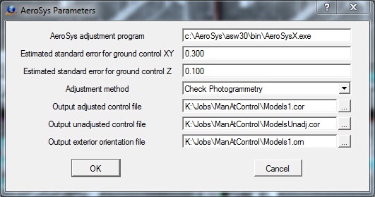
The Adjustment Parameters dialog box
Running Check Photogrammetry Adjustment
1. Press "Adjust params" (button 9) from the Main menu in Layout.
2. Set Adjustment Method to Check Photogrammetry, which will report on the quality of the point observations.
3. Press "Adjust" (button 8) to run the block adjustment.
The VrAirTrig Layout window Main Menu Keys dialog box
The following is a portion of the main report generated from the "Check Photogrammetry" adjustment. The adjustment in this example shows point 102 as a blunder point. Point 102 is highlighted in the photo point list with a <== symbol. After an adjustment, the "Drive Control" function could be used to drive to a suspect point in Layout and possibly run the Remeasure function to adjust one or more of the measurements.
-------------------------------------------------------------------------
VRAT - CHECK PHOTOGRAMMETRY REPORT
FileName : c:\Jobs\AeroSys\VrAeroSys.rep
Date Time : 8-Jul-2009 22:18:33
Adjustment Mode : Check Photogrammetry
Number of strips : 2
Number of Photos : 8
-------------------------------------------------------------------------
PHOTOGRAMMETRY RESULTS
The results shown in this report are unit-less statistics.
It is intended to show the results of the photogrammetric measurements.
The ground control was not used during the adjustment.
Results over 3.0 indicate a blunder and are noted with <==
-------------------------------------------------------------------------
BLUNDER POINTS
1 point:
102
-------------------------------------------------------------------------
ALL POINTS BY PHOTO
Photo 1003
102 3.78 5.13 <==
101 0.15 0.15
3782 -1.13 -1.13
21 -0.69 0.33
01043 0.22 -0.53
01042 -0.28 -0.23
01041 -0.16 0.46
02103 -1.32 -1.75
01033 0.63 0.63
01032 -0.86 -0.86
01031 -1.45 -2.35
Photo 1004
102 -0.43 -5.52 <==
101 -0.15 -0.15
9 0.27 0.27
3782 1.13 1.13
21 0.13 -0.12
01053 -0.00 -0.01
01052 0.11 -0.16
01051 0.40 -0.10
01033 -0.63 -0.63
01032 0.86 0.86
01031 -0.33 2.44
02123 0.03 -0.12
02103 0.22 1.78
01043 -0.28 0.48
01042 0.24 0.12
01041 -0.14 -0.17
Photo 1005
8 -0.00 -0.00
176 -0.01 0.26
9 -0.27 -0.27
21 -0.19 0.14
01063 -0.00 -0.00
01062 0.18 0.18
01061 0.08 -0.17
01043 0.32 0.04
01042 -0.22 0.11
01041 0.26 -0.19
-------------------------------------------------------------------------
Running a Full Adjustment
1. Press "Adjust params" (button 9) from the Main menu in Layout.
2. Set Adjustment Method to Full.
3. Press "Adjust" (button 8) to run the block adjustment.
The following is a portion of the main report generated from the "Full" adjustment. The adjustment shows a high residual in the Y axis on point 21. This line is shown with an <== at the end. After an adjustment the "Drive Control" function could be used to drive to a suspect point in Layout and possibly run the Remeasure function to adjust one or more of the measurements.
-------------------------------------------------------------------------
VRAT - FULL ADJUSTMENT REPORT
FileName : c:\Jobs\AeroSys\VrAeroSys.rep
Date Time : 8-Jul-2010 22:48:23
Adjustment Mode : Full
Number of strips : 2
Number of Photos : 8
-------------------------------------------------------------------------
CONTROL POINT RESIDUALS (RMS)
X Y Z
0.180 0.246 0.250
-------------------------------------------------------------------------
RESIDUALS AND PREDICTED POSITIONS AND POINT WEIGHTS
Point Type ResX ResY ResZ WgtXY WgtZ
8 HV -0.003 0.300 0.129 0.300 0.500
9 HV -0.011 0.165 -0.091 0.300 0.500
21 HV -0.196 -0.613 0.312 0.300 0.500 <==
22 HV -0.189 0.243 0.076 0.300 0.500
33 HV -0.111 -0.030 0.486 0.300 0.500
43 HV 0.091 -0.141 -0.096 0.300 0.500
101 HV -0.232 0.270 -0.034 0.300 0.500
102 HV -0.188 -0.178 -0.313 0.300 0.500
108 HV 0.142 -0.025 -0.372 0.300 0.500
176 HV 0.298 -0.166 0.003 0.300 0.500
3782 HV 0.103 0.032 0.215 0.300 0.500
4082 HV 0.295 0.143 -0.304 0.300 0.500
01031 T 0.103 0.037 0.044
01032 P 0.000 0.004 0.000
01033 P 0.006 0.062 0.028
01041 T 0.130 0.048 0.038
01042 P 0.067 0.029 0.015
01043 P 0.009 0.015 0.004
01051 T 0.111 0.067 0.041
01052 P 0.038 0.040 0.011
01053 P 0.022 0.053 0.024
01061 T 0.029 0.038 0.008
01062 P 0.005 0.095 0.012
01063 P 0.001 0.006 0.003
02101 P 0.002 0.015 0.008
02102 P 0.003 0.055 0.000
02103 T 0.057 0.048 0.015
02111 P 0.033 0.072 0.034
02112 P 0.051 0.059 0.014
02121 P 0.014 0.088 0.044
02122 P 0.002 0.056 0.001
02123 T 0.095 0.058 0.054
02131 P 0.010 0.072 0.041
02132 P 0.004 0.105 0.019
02133 T 0.030 0.038 0.007
Point types -
V-Vertical H-Horizontal HV-Horizontal+Vertical
T-Tie P-Pass VI-Visual
L-Lake C-Check
-------------------------------------------------------------------------
Adjustment Results Reports
When a block adjustment is run in "Check Photogrammetry" mode or in "Full" mode a general report is displayed showing the results of the adjustment. There are more reports available in the C:\jobs\AeroSys folder that are more detailed than the general reports.
A block adjustment from VrAirTrig may be debugged if the user's current configuration includes the optional VrAdjust (AeroSys) package. Several methods can be used to help debug a VrAirTrig block adjustment. This process might involve identifying bad measurements and/or misidentified locations for ground control points. These methods include:
| • | Running the Check Photogrammetry adjustment. |
| • | Relaxing a control point or points by point weighting. |
| • | Driving to a measured or unmeasured control point |
| • | Remeasuring a point or points. |
After relaxing a control point or re-measuring a point, the bundle adjustment may be run again and the results checked.
Relaxing a Control Point
A ground control point may be floated or weighted, which allows the adjustment to move the point within a user-defined ground value in XY or Z.
To weight a point, click on Coordinates -> Edit coordinate file, or use the Edit Coordinate (EdiCoo) command. The Edit Coordinate command dipslays a dialog box containing the control points and their X,Y,Z and weight values (CX, CZ).
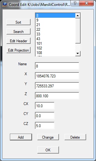
The Edit Coordinate dialog box
If the CX, CY and CZ values for a control point are zero, the "Estimated standard error for ground control XY" and the "Estimated standard error for ground control Z" will be used.. These values are set in the "Adjust params" (button 9) from the Main menu in Layout.
Setting the CX and/or CZ values to a non-zero ground value will set the weighting for that point. The CX value is used for X,Y weighting and the CY value is not used from the Edit Coordinates dialog box. After setting the weight values (relaxing a point), the bundle adjustment may be run again and the results checked. In the above Edit Coordinates dialog box, the X,Y axis is weighted with ten ground units and the Z is weighted with five ground units.
Driving to a Measured or Unmeasured Control Point
After the bundle adjustment has been run one or more times, any ground control point may be "driven to" and displayed in the Layout window. If the point measurements or location are suspect then the point may be remeasured.
To drive to a control point, click "Points" (button 3) -> "Drive control" (button 6).
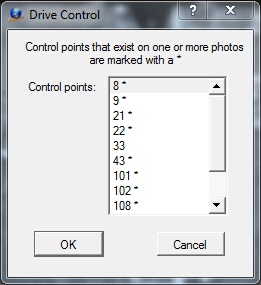
The Drive Control dialog box
The Drive Control dialog box shows all the points in the ground control file. Points that have been measured are marked with an asterisk (*). In the example dialog box above, point number 33 is shown as unmeasured. Selecting that point would show the point in all photos in Layout and prompt for an action to take on this point.
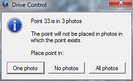
The Drive Control action dialog box
There are one of three actions that may be taken on a control point drive which include:
| • | One photo - The point will be placed in one photo. |
| • | No photos - No point placement will occur and the Layout window will display the locations of the point in the photos that it falls within. |
| • | All photos - The point will be placed in all photos that it falls within. At this time a remeasure may be started to measure the point in all qualifying photos. |
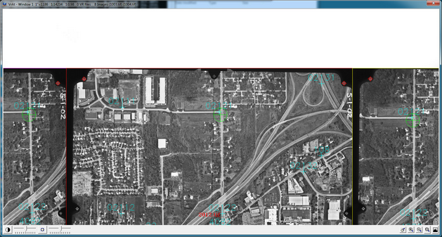
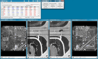
Results of Drive Control in the Layout window
In the above example, the location of point 33 is displayed in three photos with a green cross and circle.
Remeasuring a Point or Points
| • | Remeasure is a useful function that allows a single point to be remeasured on the photos that it falls within. |
| • | Remeasure can be started from Measure by clicking the "Remeasure point" (button 9). After the point is remeasured, the program will return to Measure and the results will be recalculated. |
| • | Remeasure can also be started from the Layout window by clicking "Points" (button 3) -> "Remeasure point" (button 9) and identifying the point to be remeasured. |
When Remeasure is started the photo patches will be displayed, one for each photo that the point falls within. In the following example, point 21 has been measured in six photos.
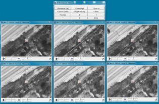
The Remeasure dialog and point photo patches
Several measurement tools are available in Remeasure, including single point remeasure, correlate and stereo measure.
NOTE: When in Remeasure, the HOLD flag is ignored, allowing the point to be remeasured on any photo.
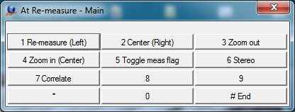
Point remeasure dialog box
After a point has been remeasured, program control returns to Measure or to Layout.
Section 7 Exporting Measurements
If performing the block adjustment with another stand-alone program is required, measurements from VrAirTrig may be exported in several different formats. Exporting measurements may also be performed if models are to be set in the Vr Orientation program using measurements as input.
Measurements may be exported from VrAirTrig by clicking Export and then choosing the format to export the measurements.
Supported measurement formats include:
| • | PATB |
| • | Albany |
| • | JFK |
| • | VrAt |