Vr Mapping |
ON-LINE REFERENCE DOCUMENTATION CARDINAL SYSTEMS, LLC |
Vr Image Utility
Type: Stand-alone application (imageutil.exe)
Vr Image Utility provides functions to facilitate management and preparation of images for the Vr Mapping environment.
Change Project Location (ChaLoc)
Clear Fiducial Templates (CleFid)
Recreate Fiducial Templates (CreFid)
Print Inner Orientations Report (PriInn)
Apply Levels Adjustment (AppLev)
Convert Exterior Orientation File (ConExt)
Image Utility contains many useful image functions. It should be the starting point for projects which use VrTwo Orientation, VrOrtho, or VrAirTrig software. Image Utility provides the following main features:
| • | Image settings management (assigning camera settings, strip locations, and name formats). |
| • | Inner Orientation in manual and automatic modes. |
| • | Camera file creation and editing. |
| • | Batch image rotations in 90 degree intervals. |
| • | Batch image pyramid creation. |
| • | Batch image format conversion. |
| • | Image Pixel size computation. |
| • | Exterior Orientation format conversion. |
The Vr Image Utility program starts by opening the Main Window and the Image Viewer Window.
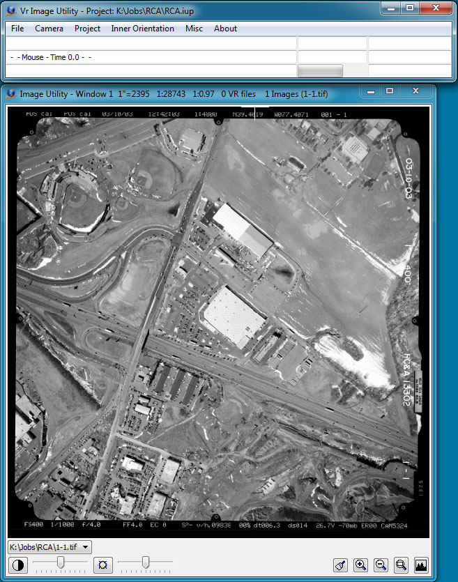
The Vr Image Utility environment showing the Main Window and the optional Image Viewer window
Starting an Application (Command)
Start commands by selecting an item from a dropdown menu. Alternatively, start commands with a key-in using the command name.
The Main Window
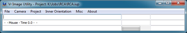
The Vr Image Utility Main Window
The Main Window in Vr Image Utility contains the command pull down menus, a key-in area, two information areas, a progress bar, and the coordinate display. Enter commands in the key-in area. The active project's name is shown in the Main Window's border.
The Image Viewer Window
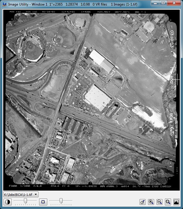
The Vr Image Utility Image Viewer window
The image viewer window allows any image in the current project to be quickly reviewed. Directly below the image, a drop-down box contains a list of all of the images in the current project. Select any image from the list to display it. In addition to the view control icons at the bottom of the image preview window, the standard VrOne zoom keys (PgDn, PgUp, Home, etc.) can change the view.
Close the image viewer window at any time by selecting the close icon in the upper right corner. It may be opened again using the Open Image Viewer (OpeIma) command or by selecting File -> Open Image Viewer pull-down.
Some of the Vr Image Utility features require a project to be defined; others are miscellaneous utilities that work without a project. A project in Image Utility comprises a list of images and camera files. The "Edit Project" command and all commands under the "Inner Orientation" pulldown require a defined project. None of the commands under the Misc. pull-down menu require a defined project.
Image Utility should be the first program used when setting up a new job for VrOrtho, VrAirTrig, or VrTwo Orientation software. A typical work flow for creating an ortho photo could be:
| 1. | Obtain raw images. |
| 2. | Run Image Utility. |
| 3. | If no camera file exists for images, create a camera definition file using Camera -> New Camera. |
| 4. | Create a new Image Utility project using Project -> New Project. The project editor dialog should be displayed. |
| 5. | Add the camera definition file to the list of project cameras. |
| 6. | Add all images to the project and define the correct strip location, pixel size, and image name format for each image. NOTE: Image name format is only important if using VrAirTrig. |
| 7. | Perform inner orientation on all images using Inner Orientation -> Automatic or Inner Orientation -> Single Image commands. NOTE: At least one image per strip location must be measured manually before using Automatic mode. |
| 8. | Run VrOrtho. |
| 9. | Create a new project. |
| 10. | Define standard VrOrtho project parameters and import the Image Utility project file. VrOrtho will recognize the image settings and inner orientations completed using Image Utility. |
| 11. | Define ortho areas for the Images. |
| 12. | Create ortho output images. |
File
Edits program preferences, opens the Image Viewer, and exits the program.
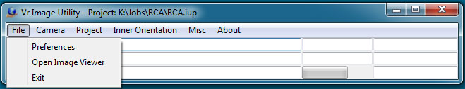
The Vr Image Utility File menu
Sets operating parameters.
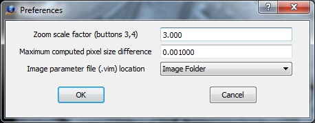
The Preferences dialog box
Zoom scale factor (buttons 3, 4)
Sets the scale factor to use while zooming in and out.
Maximum computed pixel size difference
Defines the maximum difference between the computed pixel size and the entered pixel size without a warning being displayed upon exiting Interior Orientation.
Image parameter file (.vim) location
Each image used in the Vr Image Utility program has an associated parameter (.vim) file. This file contains the interior orientation values and other image parameters. The image parameter file has the same name as the image but has a .vim file extension. These parameter files may be stored in the same directory as the images ("Image Folder") or they may be stored in the project folder ("Project Folder").
Opens the Image Viewer window if it is not currently displayed.
Exits The Vr Image Utility program.
Camera
Creates and edits camera calibration parameters.
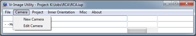
The Vr Image Utility Camera menu
Creates and edits a new camera calibration file. Prompts the user for the new camera's file name. Camera files in Vr Mapping have the .cam file name extension.
Edits an existing camera calibration file. The edited camera does not need to be one of the current cameras. Any existing camera file may be edited. When edit camera starts, it prompts the user for a camera file name. Upon exiting, the user has the opportunity to save the modified camera calibration parameters.
|
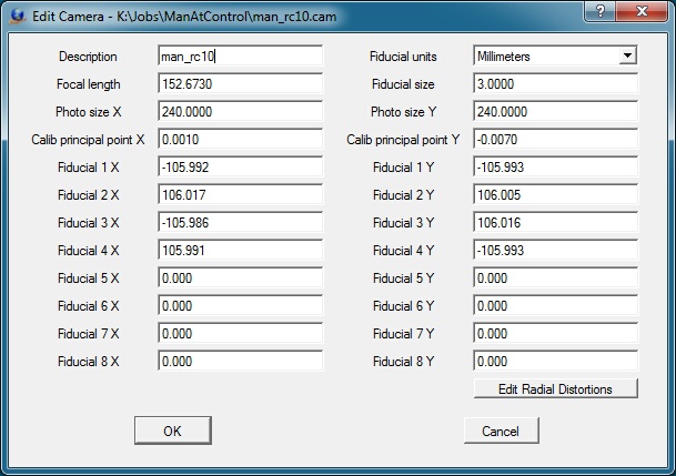
The Edit Camera dialog box
Description
Describes the camera for user reference. This description is for information only and is not used in model orientation.
Fiducial units
Specifies the units of the coordinate positions (millimeters, inches, or pixels). Many programs used to calibrate handheld cameras output the focal length of the camera in pixels. The coordinates entered to represent the fiducial positions must be in the same units as those specified here.
Focal length
Defines the camera lens' focal length, the distance from the focal point to the center of the lens. This value is provided by the camera calibration report. Focal length units should be the same as those used for the fiducial positions.
Photo size X Y
Specifies image dimensions. Photo size dimensions should be the same as those used for the fiducial positions.
Calib principal point X Y
Specifies the calibrated principal point (also known as the point of best symmetry). This coordinate position is available from the camera calibration report. Calibrated principal point coordinate units should be the same as those used for the fiducial positions.
Fiducial X Y
The coordinate positions for up to eight fiducials may be entered and must be in the user-specified Fiducial units. Most aerial cameras have eight fiducials. It is strongly recommended that all eight be entered and used to compute interior orientation. If only four fiducials are used, errors may occur and make residuals useless in determining if the wrong camera calibration was selected.
Lens distortion causes image positions to be displaced from their ideal or true locations. In aerial cameras, these distortions are normally minimal but they can still have an effect on accuracy. Some digital cameras have large lens distortions and radial distortions must be entered for accurate mapping results.
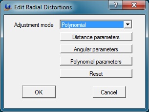
Adjustment mode
Most camera calibration programs output radial distortion values as polynomial parameters. Though angular parameters are listed, this output type is currently unsupported.
Distance Parameters
Radial distortions, represented by concentric rings about the camera lens' calibrated principal point, may be entered as distance parameters. The radial distortions shown below are from a small format camera and show high radial distortion values.
Lens distortion causes imaged positions to be displaced from the ideal or true locations. In aerial cameras these distortions are normally minimal but can still have an effect on accuracy. Some of the digital cameras have large lens distortions and radial distortions must be entered for accurate mapping results.
Adjustment mode
There are two methods of representing radial distortions which are by distance or with polynomial values. Most camera calibration programs output radial distortions values as polynomial parameters. Note that Angular parameters are listed as an option as one of the adjustment modes but this method is currently unsupported.
Distance Parameters
Radial distortions that are represented as concentric rings about the camera lens calibrated principal point may be entered as distance parameters. The radial distortions shown below are from a small format camera and show high radial distortion values.
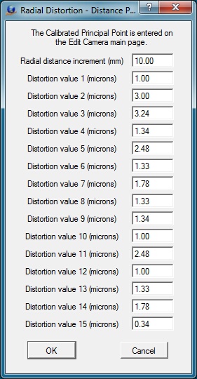
Defining radial distortions by distance
Radial distance increment
Represents the distance between the concentric rings that make up the distance parameters. Radial distance increment units should be the same as those used for Fiducial positions.
Distortion value n
Specifies distortion values for each distance. There may be up to 15 values. Distortion value units should be the same as those used for Fiducial positions.
Angular Parameters
Computation of radial distortions by angular parameters is currently unsupported. Please use distance or polynomial parameters.
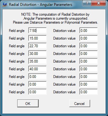
Defining radial distortions by angle
Polynomial Parameters
The polynomial values and principal point or autocollimation are provided by the camera calibration report. The mathematical model used is based on the Simultaneous Multi-camera Analytical Calibration (SMAC) method. Care should be taken when entering these parameters, as entry errors cause model orientation errors and distortions which affect model accuracy.
Entry of Exponential Notation
The k0-k4 values and the p1-p4 values are entered into the Polynomial Parameters dialog box in exponential notation. The values entered from the USGS camera calibration report may have the decimal place moved one position to the left depending on the number entered. For example:
USGS value: 0.1403x10⁻³
Value typed: .1043e-3
Shown value: 1.403000e-004
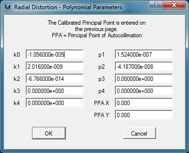
The Radial Distortions dialog box for entering the polynomial parameters
K0-K4
Defines up to five K coefficient values. These are coefficients of symmetric radial lens distortion from the camera calibration report. These values are entered in exponent form.
P1-P4
Defines to four P coefficient values. These are the coefficients of de-centering distortion from the camera calibration report. These values are entered in exponent form.
PPA X Y
Defines the principal point of autocollimation as provided by the camera calibration report.
Project
The Project menu is used to manage projects and project parameters.
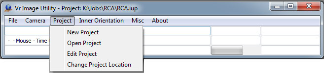
The Vr Image Utility Project menu
Creates a new project.
Opens an existing project.
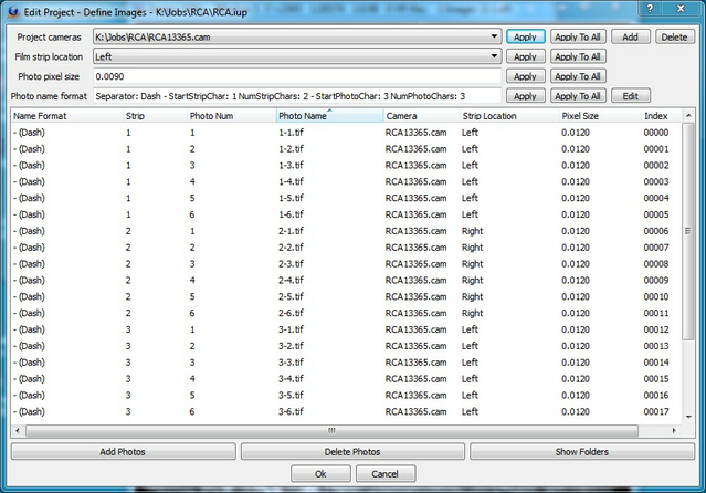
The Edit Project dialog box
The Edit Project dialog box allows all images to be added to the project and defined. Pressing “Add Photos” displays a dialog to select and add photos to the project. Pressing “Delete Photos” deletes all highlighted photos. Pressing “Hide Folders” hides the folder locations of the image and camera names. The “Hide Folders” button will change to “Show Folders” when pressed. It then can be used to display the folder locations again.
To define a setting for all images, set the appropriate value and press “Apply To All” next to the setting. To define a setting for individual images, highlight the images first, then press the “Apply” next to the setting. The currently-defined settings are applied to new photos as they are added to the project.
Project cameras
Multiple cameras may be defined for a project. Use “Add” to add cameras to the project (the camera definition file must already exists). Use “Delete” to remove the highlighted camera from the project. Up to ten camera (.cam) files may be defined for a single project.
Film strip location
Sets the location of the camera's data strip in reference to the rotation of the image. This parameter is not dependent on the direction of flight, but rather on the orientation of the image as viewed by the user. See Film Strip Location.
Photo pixel size
Sets the size of each pixel based on the fiducial coordinate units. This is normally expressed in millimeters, but may be in inches or pixels. If the fiducial coordinate units are "pixels",the photo pixel size must be 1.
Photo Name Format
Determines the format for and initial position of pass points. See Point Name Format for more information.
Changes the project file locations when project files are moved from one directory or drive to another. A dialog displays, allowing an existing Vr Image Utility project file to be selected. Once the file is selected, the following dialog is displayed.
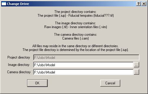
The Vr Image Utility Change Drive dialog box
Project Directory
Shows the current project directory.
Image directory
Defines the location of the directory containing the images for the project.
Camera directory
Defines to location of the directory containing the camera files for the project.
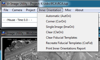
Inner Orientation
Inner (Interior) Orientations may be performed using several methods in Vr Image Utility. These methods include:
| • | Automatic - Fiducials are found on each image and the Interior Orientation is computed automatically. |
| • | Corner - Fiducials are determined from file size parameters. Use for images without fiducials or reseau points. |
| • | Single Image - Fiducials are measured manually on a single image. |
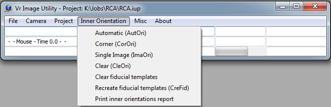
The Vr Image Utility Inner Orientation menu
Finds the fiducials on each image and automatically computes the orientations.
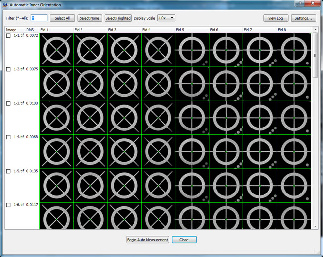
The Automatic Inner Orientation dialog box
Displays all images in the current project in a table format with one image per row. Each row displays the image name, total RMS value, and the fiducials numbered from 1 to 8.
If a fiducial has been measured, depending on viewing settings, it will either show the fiducial image with a green x indicating the measured location or the RMS x and y error values. If a fiducial has not been measured, it will display “Not Measured” if there is a template available for the fiducial, or “No Template” if no template has been created. Templates are created automatically when a manual inner orientation is performed on an image.
If an image has been measured, the total RMS displays to the left of the fiducial display. This number is red if the RMS exceeds the "Maximum allowed RMS value". (See Settings)
The filter entry controls which images are displayed. For example, a filter of 01* would only show images that start with the characters “01”.
Press “Begin Auto Measurement” to begin measurement of all images that are currently selected. There are several ways to select images.
| 1. | Use the checkbox beside an image name to toggle that image. |
| 2. | Single click an image name to highlight the image. Highlighting a single image then shift-clicking on another image name will select a range of images. Ctrl-clicking on an image name will toggle that image. Once all desired images are highlighted, they can be selected using the “Select Highlighted” button. |
| 3. | The “Select All” button checks all images. |
Once measurement has started, the fiducial display areas are updated as the measurements are taken. All measurements are recorded to the vrautoinner.log file.
Fiducial images may be displayed at a variety of scales using the Display Scale drop-down. 1.0x, 2.0x, 4.0x, and 8.0x are available.
Press “View Log” to display the measurement reporting log file using the Windows Notepad program
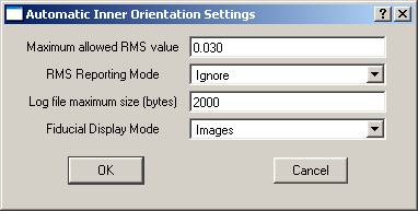
Maximum allowed RMS value
Sets the value above which any RMS figures are displayed in red. They may also be flagged in the report file depending on the Reporting Mode option.
RMS Reporting Mode
Sets the RMS reporting mode to one of three values:
| • | Ignore - Log measurement normally. |
| • | Log error and continue - Flag the measurement as being over the tolerance and continue measuring fiducials. |
| • | Log error and stop - Flag the measurement as being over the tolerance and stop measuring fiducials. |
Log file maximum size (bytes)
When fiducials are measured, the results are written to a log file in the project directory. This file is named vrautoinner.log. To keep the file from growing to an unreasonable size, you can specify the largest file size allowed. If the log file exceeds this size, it is renamed vrautoinnerlast.log and a new vrautoinner.log is started.
Fiducial Display Mode
Sets the Fiducial Display Mode to “Images” or “RMS Values”. On large jobs, using RMS Values can make it easier to scroll through the image table.
Used on digital images that contain neither fiducial marks nor reseau points. The fiducial coordinates are determined from the Photo Size X and Photo Size Y parameters.
A dialog box displays to set automatic Corner Inner Orientation on one or more images in the current project.
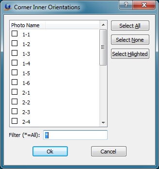
The Corner Inner Orientations dialog box
After the images are selected, press "Ok" to compute the corner inner orientations.
Manually measures an image's fiducials. This can also be used to check and edit existing measurements. The routine starts by displaying the following dialog box, which allows a single image to be selected for manual inner orientation.
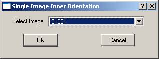
The Single Image Inner Orientation is the same process as the Interior Orientation used in VrTwo Orientation. See VrTwo Orientation - Relative Orientation.
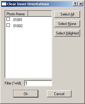
Clears the Inner Orientations of one or more images in the current project.
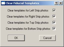
Fiducial templates can be cleared for each photo strip location. Vr Image Utility maintains one set of fiducial templates for each image strip location per project directory. In order to replace the templates for a particular image strip, they must be cleared with this option. One one image must then be manually measured using Single Image Inner Orientation.
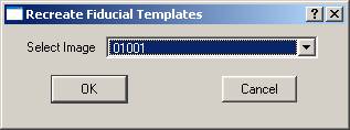
Recreate Fiducial Templates (CreFid)
The Recreate Fiducial Templates uses a single image that has already been measured to recreate fiducial templates. Once the image is selected, the fiducial templates are created using the measurements taken on the fiducials for that image. This is useful if you have changed the fiducial template size in the camera definition file and would like new templates to be created without re-measuring any fiducials.
Print Inner Orientations Report
Prints the Inner Orientation of a image or group of images. These parameters are read from existing Vr Mapping Image parameter files (.vim). Prompts the user for an output file in which to place the results. The operator can identify the .vim files to use for the report.
The following is an example of the output from this routine.
# Inner Orientations Measurements and Residuals
# Filename: c:\Texas\Houston.txt
# 16-Jul-2009 17:38:01
#
Photo K:\Jobs\RCA\1-1.vim
# Mea X Mea Y Res X Res Y
1 941.2325 18627.9156 -0.0092 0.0050
2 18706.5974 1053.0597 -0.0028 0.0051
3 1036.1506 958.0597 0.0015 -0.0052
4 18614.0494 18724.7403 0.0111 -0.0085
5 489.5974 9790.1766 0.0100 -0.0003
6 19159.6987 9890.9532 -0.0053 0.0026
7 9873.9273 505.8416 -0.0011 -0.0010
8 9774.3688 19175.9532 -0.0042 0.0022
Result: Ok
Photo K:\Jobs\RCA\1-2.vim
# Mea X Mea Y Res X Res Y
1 940.2325 18628.9156 -0.0132 0.0014
2 18701.5974 1049.0597 -0.0077 0.0027
3 1031.1506 958.0597 0.0044 -0.0006
4 18614.0494 18720.7403 0.0112 -0.0070
5 486.5974 9791.1766 0.0097 -0.0043
6 19157.6987 9886.9532 -0.0020 0.0006
7 9868.9273 503.8416 -0.0006 0.0000
8 9774.3688 19173.9532 -0.0018 0.0073
Result: Ok
Photo K:\Jobs\RCA\1-3.vim
# Mea X Mea Y Res X Res Y
1 952.2325 18643.9156 -0.0025 0.0069
2 18709.5974 1058.0597 0.0040 0.0084
3 1036.1506 973.0597 -0.0062 -0.0070
4 18626.0494 18731.7403 0.0082 -0.0135
5 495.5974 9806.1766 0.0161 -0.0030
6 19167.2164 9896.6830 -0.0038 0.0018
7 9874.9273 515.8416 -0.0042 -0.0006
8 9785.3688 19186.9532 -0.0117 0.0070
Result: Ok
Misc
Provides various image and image support routines.
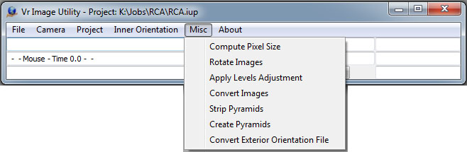
The Vr Image Utility Miscellaneous menu
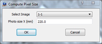
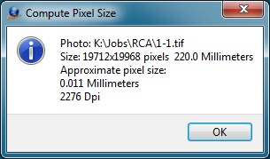
Computes the approximate pixel size of an image based on the size of the photo in pixels and a user-defined photo size. Displays the image size in pixels, the pixel size in millimeters, and the resolution of the image in "Dots per Inch" (DPI).
Rotates images 90, 180 or 270 degrees. This operation can be performed on a single image or a group of images.
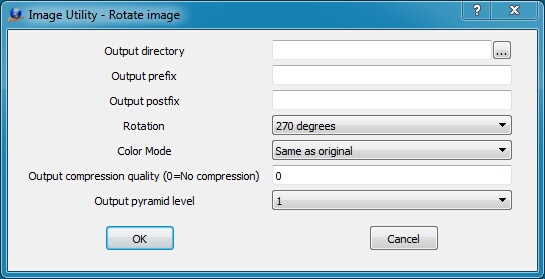
Output compression quality is only used if the input image is a JPEG file
Output directory
Specifies directory into which to place rotated files. If this field is left blank, the output files will be placed in their original directories, overwriting the original files.
Output prefix
Defines a character string to be prepend to each output file name. This field may be left blank.
Output postfix
Defines a character string to append to each output file name. This string is placed after the file name and before the file name extension. This field may be left blank.
Rotation
Sets the angle of rotation to 90, 180, or 270 degrees.
Color Mode
Defines the output color mode:
| • | Same as original – The output image uses the same color mode as the input image. |
| • | Greyscale – The output image uses grayscale color mode. |
| • | RGB – The output image uses RGB color mode. |
| • | YCbCr – The output image uses YCbCr color mode. |
Output compression quality (0=No compression)
If the input image is compressed, this setting controls the compression quality of the output image as a value from 1-100. Higher values mean higher quality and less compression. For ECW/JPEG2000 images, this field represents an approximate compression ratio. If 0 is entered, output images are written uncompressed. NOTE: It is recommended that rotations be performed on original uncompressed images. Rotations on compressed images involve un-compressing and re-compressing the image, resulting in some image quality loss.
Output pyramid level
Images may be output at a reduced resolution by selecting an Output Pyramid Level greater than 1.
Once the rotation parameters are defined, the Open Files dialog displays and one or more images may be chosen for rotation. If images are to be written back to the original file, it is recommended that these files be backed up before rotation.
Use this dialog to select all images to be rotated. The images are written back to the original file, so it is recommended a backup be made before running this routine.
Applies levels adjustment to a group of images. A single levels adjustment file may be applied to all of the images. Alternately, separate levels files may be automatically applied to each image.
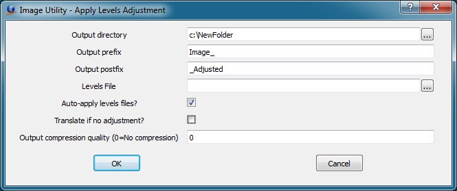
Output directory
Specifies the output directory for the new images. If this is left blank, the output directory is the same as the input image directory.
Output prefix
Specifies output prefix. The string entered here is prepended to all output image names.
Output postfix
Specifies output postfix. The string entered here is appended to all output image names.
Levels File
Defines file from which to take level adjustment parameters. This may be either a Photoshop .alv file saved from the Levels adjustment dialog or a .lvl file produced by VrOne or GIMP. This can be left blank if the “Auto-Apply levels files” is on.
Auto-apply levels files
If this is on and an image has a matching .lvl file, the .lvl file is used when applying the levels adjustment (overriding the Levels file entered above). The .lvl must have the same base filename and must be in the same directory as the image.
Translate if no adjustment
If this is on, the files will be translated even if the levels adjustment results in no changed to the image. This is useful if Auto-apply is engaged and some images have adjustment files and others do not, but all images should be copied to the output directory.
Output compression quality (0=No compression)
Controls the compression quality of the output image if the input image is compressed. A value from 1-100 may be entered. Higher numbers reflect higher quality and less compression. For ECW/JPEG2000 images, this field represents an approximate compression ratio. If 0 is entered, output images are written uncompressed. NOTE: It is recommended that rotations be performed on original uncompressed images. Rotations on compressed images involve un-compressing and re-compressing the image, resulting in some image quality loss.
Converts a group of images to a different format or name. File name pre/postfixes can be added, planar configurations can be changed, file type and color modes can be altered, compression can be added, and file size can be modified.
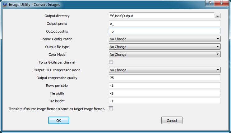
Output directory
Specifies the output directory for the converted images. If this is left blank, the output directory is the same as the input image directory.
Output prefix
Specifies output prefix. The string entered here is prepended to all output image names.
Output postfix
Specifies output postfix. The string entered here is appended to all output image names.
Planar Configuration
Determines planar configuration of the output file. The options are:
| • | No Change - The output image contains the same planar configuration as the input file. |
| • | Contiguous (pack samples contiguously (RGBRGB...) - The output image uses the Contiguous planar configuration. |
| • | Separate (store samples separately (RRR...GGG...BBB...) - The output image uses the Separate planar configuration. |
Output file type
Specifies output image file type:
| • | No Change - The output image's file type is the same as the input file's. |
| • | Tiff Scanline (uncompressed) - The output image is a standard uncompressed TIFF file. |
| • | Tiff Strip - The output image is a TIFF file using image strips (either compressed or uncompressed). |
| • | Tiff Tiled - The output image is a TIFF file using image tiles (either compressed or uncompressed). |
| • | Jpeg - The output image is a JPEG image. |
| • | JPEG2000 - The output image uses JPEG2000 compression. |
| • | ECW - The output image is an ECW image. |
Color mode
Specifies the output image color mode:
| • | None - The output image's file type is the same as the input file's. |
| • | Grayscale - The output image is grayscale |
| • | RGB - The output image is RGB color |
Output compression mode:
Specifies the output compression mode:
| • | No Change - The output image's compression mode is the same as the input file's. |
| • | None - The output image is not be compressed. |
| • | Jpeg - The output image uses JPEG compression. |
Output compression quality
Sets quality setting for JPEG compression on an output image. This is a value between 0 and 100. Higher values mean higher quality but larger file size. Compressing files multiple times or un-compressing files and re-compressing them again will result in image quality loss.
Rows per strip
If images are output in “Tiff Strip” mode, this number controls the number of rows per strip. If -1, the number of strips per row in the input image is used. A default of 16 is used if the input image is not in Strip mode.
Tile width
If images are output in “Tiff Tiled” mode, this number controls the width of each tile. If -1, then the width of tiles in the input image is used. A default of 128 is used if the input image is not in Tiled mode.
Tile height
If images are output in “Tiff Tiled” mode, this number controls the height of each tile. If -1, then the height of tiles in the input image is used. A default of 128 is used if the input image is not in Tiled mode.
Translate if source image format is same as target image format
If not checked, no translation is done if the source image format matches the target image format. This can help prevent images from being compressed multiple times.
Takes a group of images with embedded pyramid images and removes them from the embedded pyramid images. If the images are using compression, the original image will be re-compressed, so there may be some image quality loss.
Creates image pyramid files on one or more images. VrOne automatically creates image pyramid files when new images are opened. This allows image pyramids to be created for large groups of images before opening them in VrOne. Image pyramids are created either as external files or internal sub images based on the settings in Vr Configuration.
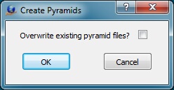
Overwrite existing pyramid files?
If checked, new pyramid files will be created for all selected images, even if they already exist. This parameter is considered only in the image pyramids are to be created as external files and not included in the original image.
Once the single parameter is defined, the Open Files dialog is displayed and one or more images may be chosen for image pyramid creation.
Convert Exterior Orientation File
Converts an Exterior Orientation file from one EO format to another supported EO format. The foloowing Exterior Orientation format are supported:
| • | ALBANY |
| • | Applanix |
| • | PATB |
| • | JFK |
| • | AeroSys |
| • | ISAT EO file |
| • | BINGO |
| • | ISAT ‘photo’ file |
| • | MATCH-AT |
See Exterior Orientation File Formats for more information about the supported Exterior Orientation formats.
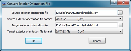
Source exterior orientation file
Defines the source or input file name.
Source exterior orientation file format
Defines the source or input orientation file format.
Target exterior orientation file
Defines the target or output file name. This file name must be different than the source exterior orientation file name.
Target exterior orientation file format
Defines the target or output orientation file format.
About
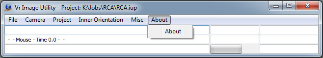
The Vr Image Utility About menu
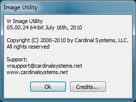
Displays a dialog box showing the current version number and release date and software build (32-bit or 64-bit).
Credits
Displays the copyrights of the third party software used by Vr Mapping.